· Updated - TITANIUM 3DP Engineering - Engineering Guides - 15 min read
Titanium 3D Printing Fatigue Design: Surface Finish, HIP, and Inspection
Engineering guide for titanium 3D printing fatigue design, covering surface finish, HIP, support scars, notches, build orientation, CT, coupons, and RFQ acceptance evidence.
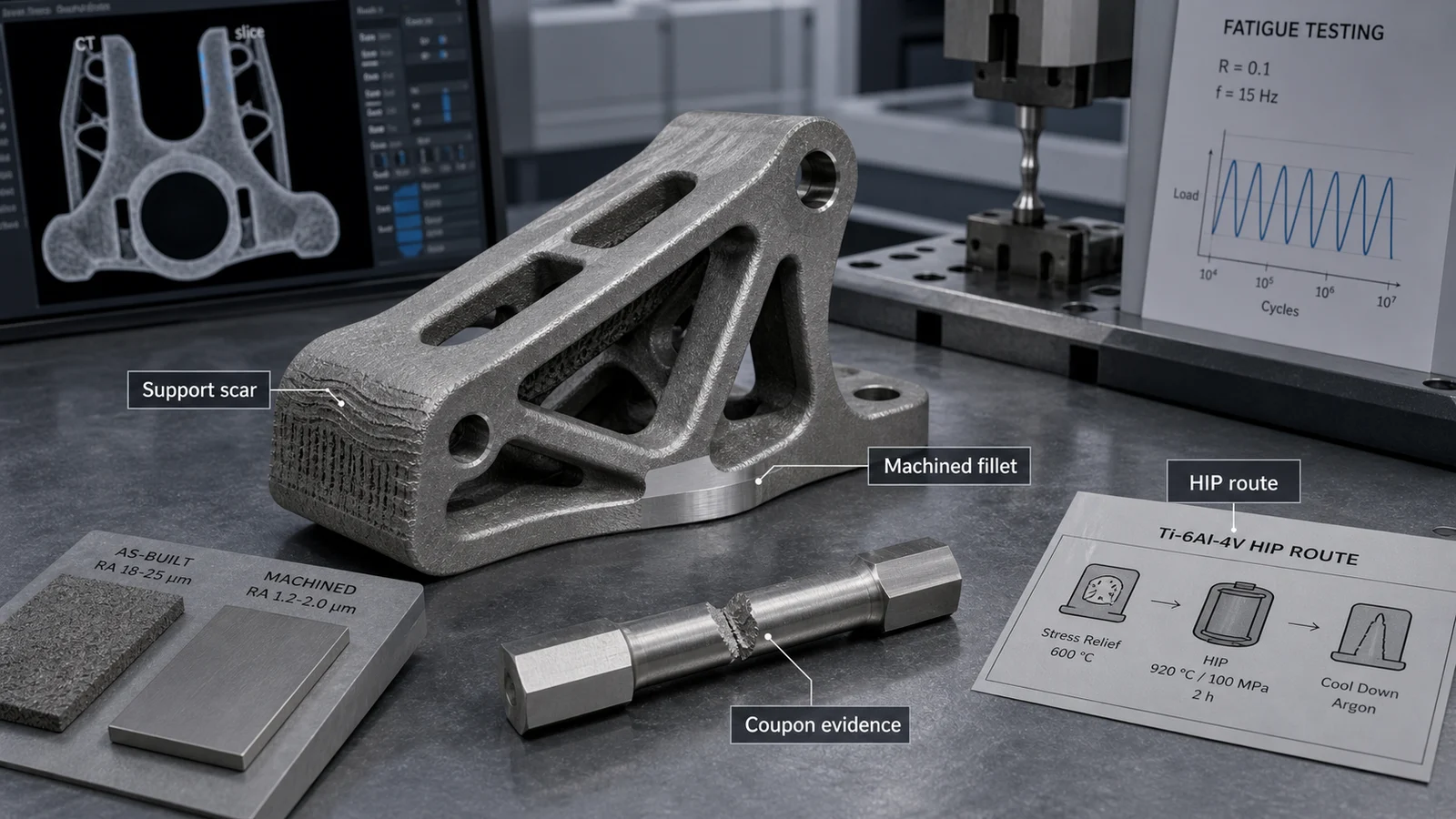
Representative article image; not a customer acceptance record or proof of a qualified manufacturing route. Refer to the cited sources and part-specific inspection records for engineering evidence.
On this page
Fatigue is one of the hardest acceptance questions in titanium 3D printing because the part can look strong in a static review and still be weak under repeated loading. In LPBF and EBM titanium parts, fatigue performance depends on geometry, surface condition, support marks, defect population, build orientation, residual stress, HIP, finishing, and how the supplier proves the route. NASA-HDBK-5026, active Baseline dated August 12, 2024, treats process variability, porosity, surface finish, post-processing, orientation, and representative fatigue data as coupled controls for NASA spaceflight hardware; it is a useful conservative evidence model, not a universal commercial requirement.
This article is not a substitute for a formal allowables program. It does not provide a universal fatigue strength, life, roughness limit, HIP cycle, or inspection threshold. ASTM F2924-14(2021) is an active specification for PBF Ti-6Al-4V components and includes minimum tensile-property requirements, but conformance to that material specification does not by itself establish a component-specific fatigue allowable, damage-tolerance case, or product approval. For US medical devices, the FDA’s additive-manufacturing guidance is device-specific and nonbinding; neither material conformance nor a successful coupon establishes clearance, approval, biocompatibility, sterilization validation, or patient suitability.
Within those boundaries, this is a practical RFQ and design guide for engineers and procurement teams who need to decide whether a titanium AM part has a credible fatigue route before price comparison begins.
Quick Answer
For fatigue-sensitive titanium 3D printed parts, do not treat printing as the only manufacturing step. Define the complete route:
- Identify fatigue-critical surfaces, radii, holes, edges, thin ribs, lattice transitions, and load-introduction regions.
- Keep supports away from fatigue-critical areas whenever possible.
- Machine or finish surfaces where roughness, support scars, or down-skin texture control life.
- Use generous radii and smooth section transitions instead of sharp weight-reduction cuts.
- Define whether stress relief, anneal, HIP, machining, polishing, shot peening, or other finishing is required.
- Specify CT, CMM, coupons, density, and traceability only where they answer the acceptance question.
- Ask the supplier to state the build orientation, post-processing condition, inspection scope, and any design changes needed before quotation.
The cheapest fatigue-critical quote is often the one that has not priced the evidence.
Why Fatigue Is Different From Static Strength
Static strength asks whether a part can carry a load once. Fatigue asks whether it can survive repeated cycles without crack initiation and growth. Titanium AM can produce strong material, but fatigue is usually controlled by local features and process history rather than by headline tensile strength alone. ASTM E466-21 identifies material, geometry, surface condition, directionality, residual stress, and surface finish among the variables that must be controlled or reported in axial fatigue testing, and limits design use of specimen results to conditions that realistically simulate service or are addressed by a defined transfer method.
Fatigue risk often starts at:
- Rough as-built surfaces.
- Down-facing surfaces.
- Support-contact scars.
- Sharp internal corners.
- Thread roots and small holes.
- Thin-to-thick section transitions.
- Lattice-to-solid transitions.
- Surface-connected porosity.
- Lack-of-fusion defects.
- Machining marks on highly stressed faces.
A tensile coupon can pass while the actual part still has a local fatigue problem. That does not make coupons useless. It means the evidence package must match the part risk.
For a broader acceptance framework, see Titanium AM Qualification and Inspection Evidence.
Start With the Load Path
Fatigue design should begin with the load path. Before asking for a quote, identify which regions see cyclic tension, bending, torsion, pressure cycling, vibration, impact, or combined loading. If the part is a bracket, manifold, mount, housing, or lightweight structure, the critical region may not be the thinnest wall. It may be a fillet, bolt boss, lattice transition, machined bore, or supported underside.
Ask these questions:
- Where can a crack start?
- Which surfaces see tensile stress during the load cycle?
- Are critical surfaces as-built, machined, polished, shot-peened, or supported?
- Are bolt holes, bores, and sealing faces loaded in a way that requires machining?
- Does the design include sharp weight-reduction pockets or thin ribs tied into thick bosses?
- Does build orientation place rough down-facing texture on a high-stress surface?
- Does the inspection plan look at the region that actually controls fatigue?
If these questions are not answered, the RFQ may compare prices for a shape rather than routes for a fatigue-capable part.
Surface Finish Controls Crack Initiation
Surface condition is one of the main fatigue drivers in titanium 3D printing. As-built LPBF and EBM surfaces can include adhered powder, stair-stepping, partially melted features, support marks, and rough down-facing regions. These features can act as local stress concentrators where cracks start. In a NIST study of PBF-EB Ti-6Al-4V, an observed fatigue benefit on smooth specimens did not carry over to as-built rough specimens because dominant crack initiation remained at deep surface-crevice roots. That bounded experiment supports controlling the actual critical surface; it is not a transferable design allowable.
Surface finish does not need to be improved everywhere. It needs to be controlled where fatigue depends on it.
Useful surface classes for the drawing are:
- As-built acceptable surfaces with no fatigue-critical function.
- Finished surfaces where roughness affects fatigue, flow, sealing, cleaning, or assembly.
- Machined surfaces for bores, threads, datum pads, bearing faces, and highly loaded interfaces.
- No-support surfaces where support scars would create unacceptable notch risk.
This avoids over-finishing the entire part while still protecting the surfaces that matter. It also prevents a supplier from placing supports on a critical face simply because the drawing did not mark the risk.
For downstream route planning, pair this with Post-Processing for Titanium 3D Printing.
Support Scars Are Fatigue Features
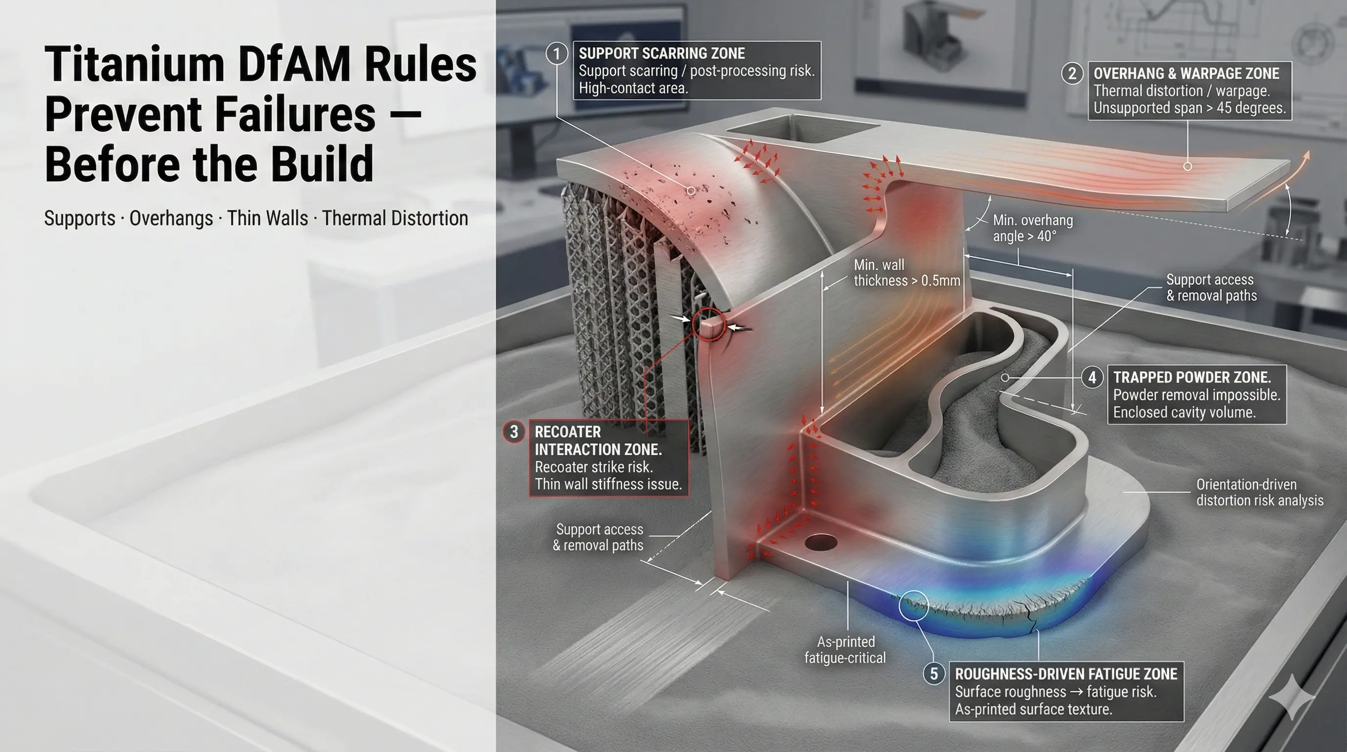
Support scars are not only cosmetic defects. They can be notch-like surface features, especially when they remain on loaded edges, thin ribs, underside faces, or transition regions. Removing supports can also introduce local gouges or hand-finished variability if the part geometry blocks access. Within its medical-device scope, the FDA additive-manufacturing guidance states that support location, type, and number can affect finished geometry and mechanical properties, and that removal can leave surface marks or residues; this supports documenting support geometry and removal, but it is not a fatigue-life value.
Support planning should be treated as fatigue planning when:
- The part has cyclic bending or vibration.
- Supports touch tensile-stressed regions.
- The surface cannot be machined after support removal.
- Support contact sits near a fillet, hole, thread, or section change.
- The support region is difficult to inspect.
- The part uses lattice or topology-optimized geometry near a load path.
Good RFQ language identifies protected surfaces and asks the supplier to propose orientation or geometry changes that reduce support contact risk. The Titanium DfAM Rules for LPBF and EBM guide covers support and orientation review in more detail.
HIP Helps Internal Defects, Not Every Fatigue Risk
HIP can be valuable for titanium AM because it can reduce internal porosity when the defect population is part of the fatigue risk. But HIP is not a universal fatigue solution. It does not remove sharp geometry, polish rough surfaces, erase support scars, create better datums, or prove that a part is safe.
A 2024 NIST PBF-L Ti-6Al-4V study compared 800 °C, 920 °C, and 1050 °C HIP conditions using machined cylinders from one build, 30 tests per condition, and fully reversed rotating-bending loading (R = -1). The different HIP temperatures produced different microstructures and fatigue responses. Those are study conditions, not recommended production setpoints; the result supports treating the HIP cycle and resulting microstructure as controlled variables rather than applying a universal fatigue-improvement factor.
HIP is strongest when it is part of a controlled route:
- Print with controlled parameters and traceable powder.
- Stress relieve or heat treat according to the supplier route.
- HIP under defined conditions when the risk justifies it.
- Machine or finish fatigue-critical surfaces.
- Inspect features and defects that matter to acceptance.
- Document the post-processing batch and part condition.
HIP should be specified because the fatigue route requires it, not because it sounds like a quality upgrade. If HIP is quoted, cite the governing material or post-processing specification and exact accepted revision, define the validated cycle and final material condition, and ask whether inspection happens before HIP, after HIP, or both. ISO/ASTM 52908:2023 provides current PBF requirements for finished-part qualification, quality assurance, post-processing, inspection, and testing, but the purchaser still has to define the required quality level and acceptance basis.
Geometry: Notches, Radii, and Lattice Transitions
Many titanium AM fatigue problems are designed into the part before the build starts. Additive manufacturing makes it easy to create weight-reduction pockets, ribs, lattice regions, and organic shapes, but these features still need clean load transfer.
High-risk geometry includes:
- Sharp internal corners.
- Abrupt thin-to-thick transitions.
- Small holes near loaded edges.
- Threaded features printed without machining allowance.
- Unsupported overhangs on tensile-stressed faces.
- Lattice struts connected directly into a hard load path.
- Topology-optimized shapes with small local necks.
- Cosmetic lightweighting that does not improve system behavior.
Better fatigue design uses generous radii, smooth thickness changes, machined or finished load-introduction regions, and clear separation between structural lattice regions and precision interfaces. If a lattice is used, the RFQ should define whether it is structural, damping-related, flow-related, or only for mass reduction.
For application screening, see Titanium Additive Manufacturing Applications That Achieved Real Weight Reduction.
Build Orientation and Anisotropy
Build orientation affects surface quality, support placement, thermal history, distortion, and mechanical response. A fatigue-sensitive part should not treat orientation as a supplier-only detail. If orientation changes, the support scars, down-facing surfaces, coupon relevance, and inspection basis may change with it. For NASA spaceflight hardware, NASA-HDBK-5026 recommends fatigue data and coupons that represent or conservatively envelope orientation, surface condition, anisotropic stress state, residual stress, feedstock, machine family, and post-processing; other programs need their own approved transfer basis.
The RFQ should ask the supplier to state:
- Proposed build orientation.
- Support locations and removal method.
- Which critical surfaces are down-facing.
- Whether machining stock is required.
- Whether coupons represent the same orientation or post-processing condition.
- Whether any fatigue-critical region has process-specific risk.
This does not mean the buyer must lock orientation before supplier review. It means orientation should be documented and controlled once the route is accepted.
CT, Coupons, and Evidence Limits
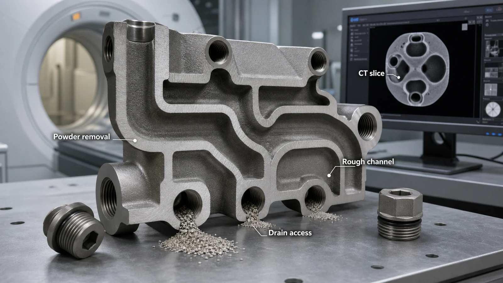
Inspection evidence is useful only when it answers the right question. CT can help evaluate internal defects, wall thickness, hidden geometry, trapped powder, and some porosity conditions. It cannot prove every possible fatigue problem is absent. A NIST study of XCT acquisition parameters and probability of detection found that acquisition settings affected image noise and defect-detection performance. A fatigue-critical CT requirement therefore needs a defined part region and orientation, scan and reconstruction procedure, target flaw type and size, analysis threshold, probability-of-detection or other qualification basis, and acceptance rule; a nominal voxel size or a statement that the part “passed CT” is not enough. ISO/ASTM TR 52905:2023 surveys NDT methods applicable to AM defect classes, but it does not supply a universal part acceptance threshold.
Tensile coupons can confirm material response for a build or post-processing condition. Fatigue coupons can be more relevant when fatigue behavior is the main acceptance concern, but they must be tied to the build orientation, surface condition, and post-processing condition being evaluated. ASTM F2971-13(2021) standardizes reporting of AM specimen material and processing history, while ASTM E466-21 covers constant-amplitude, force-controlled axial fatigue testing in air at room temperature and explicitly does not cover full-scale components. A polished coupon does not prove an as-built support-scarred surface will survive, and a coupon tested under one load mode or environment does not automatically qualify another.
Evidence options include:
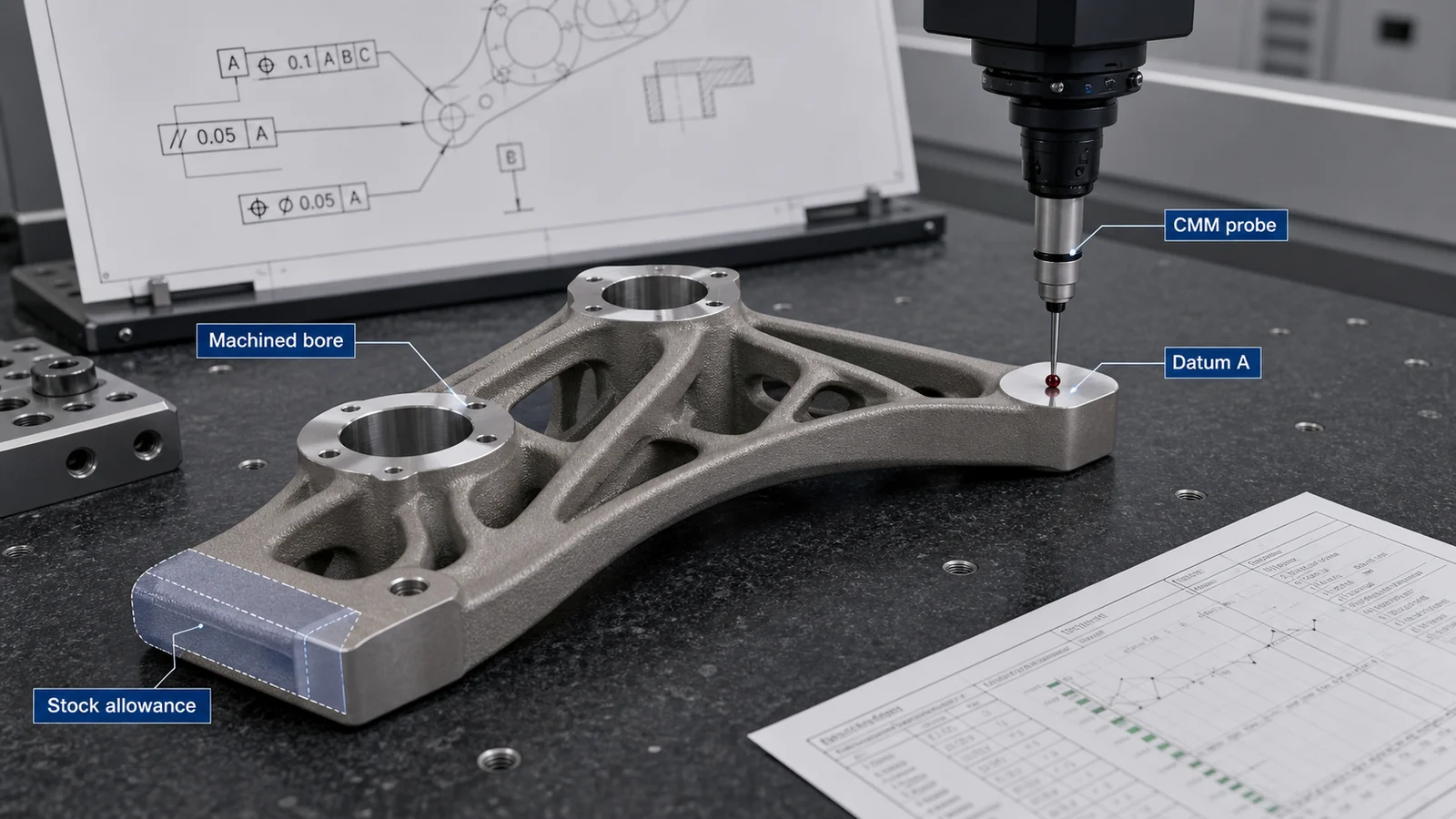
- CMM report for datums, bores, and load-interface geometry.
- CT report for internal defects, wall thickness, trapped powder, or porosity risk.
- Tensile coupons tied to build lot and heat-treatment condition.
- Fatigue coupons when program risk requires fatigue evidence.
- Density or metallography where defect morphology matters.
- Surface roughness measurement on defined surfaces.
- COA, COC, build record, powder lot, post-processing batch, and inspection report.
The evidence package should be proportional to risk. Under-specifying evidence delays approval. Over-specifying evidence adds cost without improving the decision.
RFQ Scenario: Lightweight Bracket With Support Scars
Consider a Ti-6Al-4V bracket redesigned for weight reduction. The CAD model removes mass with thin ribs and a pocketed underside. A print-only quote looks attractive because the part is small and the material volume is low.
The fatigue route may tell a different story. If the pocketed underside needs supports and sees cyclic tensile stress, support scars could control life. If the bolt bores are printed without machining allowance, local fit and load transfer may be inconsistent. If the lattice transition sits near a bolt boss, the crack initiation region may be hard to inspect.
A better route may include:
- Reorienting the part to protect the loaded underside.
- Adding machining stock around bores and datum pads.
- Increasing local radii at rib transitions.
- Moving lightweight pockets away from high-stress regions.
- Using stress relief and HIP when risk justifies it.
- Finishing or machining fatigue-critical surfaces.
- Adding CMM and CT only where they support acceptance.
- Using representative coupons for the build and post-processing condition.
The revised route may have a higher print price but a lower approval risk. That is the number procurement should compare.
Cost Trade-Offs
Fatigue controls can increase cost, but the wrong savings are expensive. Cutting HIP, finishing, machining stock, or inspection may reduce the first quote while increasing rework, test failure, or approval delay.
Cost should be reviewed as a risk ledger:
- Can a geometry change remove the need for support on a fatigue surface?
- Can machining be limited to functional interfaces instead of all surfaces?
- Can surface finish be specified only where fatigue depends on it?
- Can CT scope focus on the critical region instead of scanning without a decision rule?
- Can coupons be tied to the actual acceptance question instead of requested generically?
- Can the part be redesigned so conventional machining is better for fatigue-critical features?
For broader quote normalization, use Titanium 3D Printing Cost Drivers: How to Reduce RFQ Price and the Titanium AM RFQ and Procurement Guide.
RFQ Checklist for Fatigue-Sensitive Titanium AM
Send the supplier:
- STEP file and drawing with datums.
- Target alloy, applicable material or part specification, exact revision, part class, and any supplementary requirements; do not use “Ti-6Al-4V” alone as the acceptance specification.
- Quantity, build lot, and target lead time.
- Description of cyclic load, vibration, pressure cycling, or fatigue concern.
- Required life or load spectrum, stress ratio, frequency, temperature, environment, failure definition, statistical basis, and program-specific design or scatter factors.
- Fatigue-critical surfaces, edges, holes, radii, and load interfaces.
- No-support surfaces and surfaces allowed to remain as-built.
- Required machining stock for bores, threads, datum pads, and loaded faces.
- Required post-processing and accepted final condition: stress relief, HIP, machining, polishing, shot peening, cleaning, and the governing procedure or specification.
- Surface roughness requirement only where function requires it.
- Applicable fatigue test method, specimen geometry, orientation, surface state, post-processing state, loading mode, environment, and transfer basis to the part.
- Inspection scope and acceptance rules: CMM, qualified CT, coupons, surface roughness, density, or other evidence.
- Documentation package: COA, COC, build record, powder lot, post-processing batch, inspection reports.
- Permission for the supplier to recommend DfAM changes before final quotation.
This information lets the supplier quote a delivered fatigue-capable route instead of a print-only shape.
Better RFQ Wording
Weak wording:
Quote this titanium 3D printed bracket. It needs good fatigue strength.
Better wording:
Please review this Ti-6Al-4V bracket for LPBF or EBM. The part sees cyclic bending at the two mounting bosses and the underside rib transition. Please identify support-contact risk, proposed build orientation, required machining stock, surface finishing for fatigue-critical regions, whether HIP is recommended, and the inspection evidence needed for acceptance. Quote the delivered part, not print-only pricing.
This wording gives the supplier enough engineering context to flag risks and enough procurement structure to compare quotes fairly.
When to Avoid Titanium AM for Fatigue Parts
Titanium AM may be the wrong route when:
- The part has simple geometry that is easy to machine.
- All fatigue-critical surfaces require tight machining anyway.
- The project cannot budget the evidence required for acceptance.
- The design includes inaccessible support scars in high-stress areas.
- Internal defects or surface roughness cannot be inspected or controlled.
- Available fatigue data do not represent or conservatively envelope the accepted machine, feedstock, orientation, surface condition, post-processing route, load mode, and service environment.
- The buyer expects a drop-in forging replacement without redesign and qualification.
- High production volume makes forging, machining, casting, or a hybrid route stronger economically.
The no-go screening guide is here: When Not to Use Titanium Additive Manufacturing.
Bottom Line
Fatigue-sensitive titanium 3D printed parts require a route, not just a print. Surface finish, support scars, geometry, HIP, build orientation, machining, CT, coupons, and traceability all influence whether the part can be accepted.
The best RFQ makes the fatigue risk visible before quotation. It identifies where cracks could start, which surfaces need protection, what post-processing is required, and which evidence will be used to approve the delivered part. That is how titanium AM moves from an attractive lightweight CAD model to a credible production component.
Official Sources and Scope
Standards status was checked on July 24, 2026. The drawing, purchase order, and qualification plan should cite the exact accepted revision because standards and program requirements can change.
- NASA-HDBK-5026, Guidance on Strength, Fatigue, and Fracture Control Requirements for Additively Manufactured Spaceflight Hardware, active Baseline dated August 12, 2024. NASA-specific implementation guidance; not a universal commercial acceptance standard.
- NASA-STD-6030, Additive Manufacturing Requirements for Spaceflight Systems, active Baseline dated April 21, 2021. Applies to NASA spaceflight hardware within its stated scope or when contractually invoked.
- ASTM F2924-14(2021), Standard Specification for Additive Manufacturing Titanium-6 Aluminum-4 Vanadium with Powder Bed Fusion. A material/component specification, not a stand-alone fatigue-life or product-approval standard.
- ASTM E466-21, Standard Practice for Conducting Force Controlled Constant Amplitude Axial Fatigue Tests of Metallic Materials. Its stated scope is specimen testing under defined axial, constant-amplitude, room-temperature-air conditions, not full-scale component qualification.
- ASTM F2971-13(2021), Standard Practice for Reporting Data for Test Specimens Prepared by Additive Manufacturing. Supports traceable reporting of specimen material, processing, and post-processing history.
- ISO/ASTM 52904:2024, Metal Powder Bed Fusion Process to Meet Critical Applications, and ISO/ASTM 52908:2023, Post-processing, Inspection and Testing of PBF Parts. These govern process-control and finished-part evidence frameworks; application-specific requirements still control.
- ISO/ASTM TR 52905:2023, Defect Detection in Metal AM Parts. A technical report on applicable NDT methods and defect classes, not a universal defect-size acceptance table.
- NIST: Microstructural Effects on Rotating-Bending Fatigue of PBF-L Ti-6Al-4V With Different HIP Treatments, published April 30, 2024; NIST: Surface Globularization and PBF-EB Ti-6Al-4V Fatigue, published February 26, 2022. Both are bounded experiments and should not be reused as design allowables without a qualified transfer basis.
- NIST: Influence of XCT Acquisition Parameters on Image Quality and Probability of Detection of AM Defects, published November 28, 2019. Supports procedure-specific CT qualification rather than a generic “CT passed” claim.
- FDA: Technical Considerations for Additive Manufactured Medical Devices, final guidance issued December 2017. It states FDA’s current thinking and does not replace device-specific regulatory requirements.
- Fatigue
- Surface finish
- HIP
- LPBF
- EBM
- DFAM
- Inspection
- RFQ