· Updated - TITANIUM 3DP Engineering - Engineering Guides - 12 min read
Titanium 3D Printed Internal Channels: Powder Removal and CT
Engineering guide for titanium 3D printed internal channels, powder removal, trapped-powder risk, CT inspection, cleaning access, surface finish, and RFQ acceptance criteria.
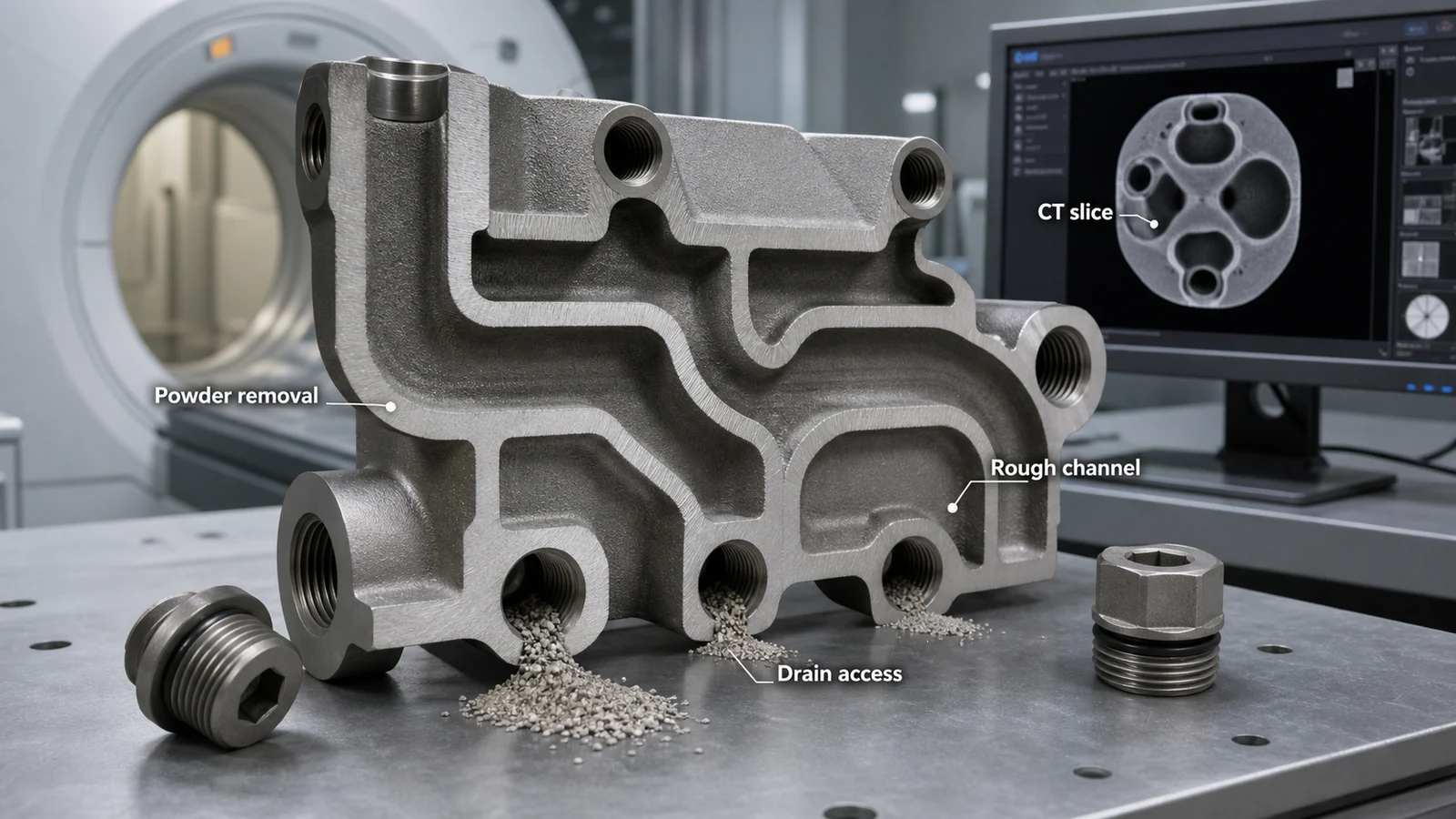
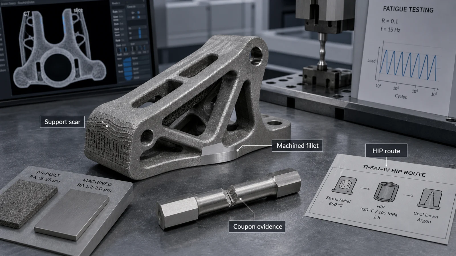
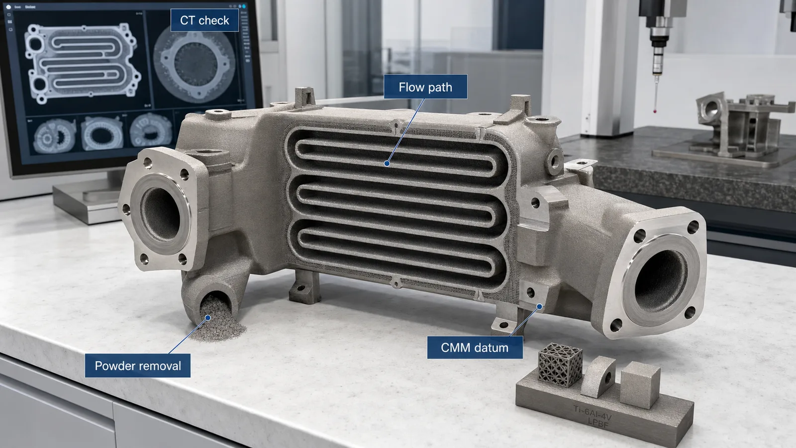
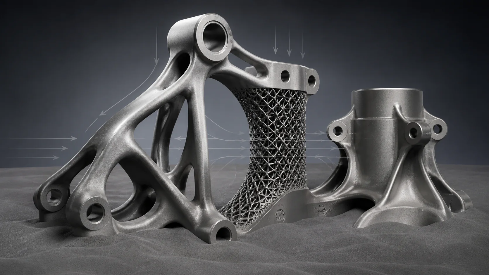
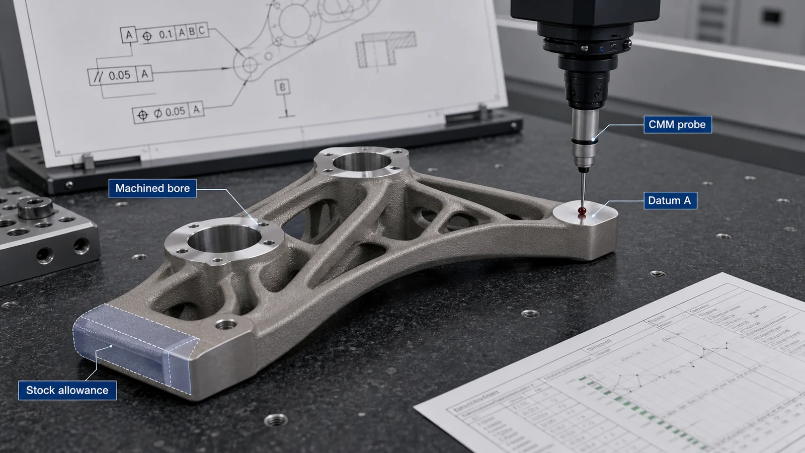
Representative article image; not a customer acceptance record or proof of a qualified manufacturing route. Refer to the cited sources and part-specific inspection records for engineering evidence.
On this page
Titanium 3D printed internal channels can justify additive manufacturing when they remove fittings, reduce assembly joints, route flow through compact geometry, or place fluid paths where machining cannot reach. They are also one of the fastest ways for a titanium AM project to fail if powder removal, cleaning, CT inspection, surface condition, and acceptance criteria are left until after the quote.
The best internal-channel RFQs do not ask only whether the shape can be printed. They ask whether the channel can be depowdered, inspected, cleaned, pressure tested, finished where needed, and documented well enough for the part to be accepted.
Quick Answer
Use titanium 3D printing for internal channels when the channel geometry creates functional value and the acceptance route is clear. Before requesting a quote, define:
- Alloy grade, such as Ti-6Al-4V, Ti-6Al-4V ELI, or CP titanium.
- Process openness, usually LPBF or EBM for enclosed internal geometry.
- Minimum channel size and the smallest intentionally open feature.
- Powder exit locations and cleaning access.
- Flow, pressure drop, pressure test, or leak requirement.
- Whether internal roughness affects performance.
- CT scope, detection threshold, and pass/fail rule.
- Whether residual powder, partial blockage, or rough internal surfaces are rejectable.
If the channel cannot be cleaned or verified, it should be redesigned before procurement compares prices.
Why Internal Channels Are a Strong Titanium AM Use Case
Internal channels are valuable because they change the product architecture, not because they look complex. A printed titanium manifold, valve body, heat-management part, hydraulic component, or compact duct can replace drilled cross holes, plugs, brazed joints, welded tubes, and multi-part assemblies.
This can create real value when the project needs:
- Curved flow paths that cannot be drilled conventionally.
- Compact routing through a structural bracket or housing.
- Fewer leak paths and fewer external fittings.
- Lightweight hydraulic or pneumatic manifolds.
- Corrosion-resistant titanium flow paths in aggressive environments.
- Patient-specific or packaging-driven routing where conventional tooling is impractical.
- Low-volume parts where tooling, welding, or assembly cost is the bottleneck.
The same geometry can become a liability if the channel is treated as a hidden CAD feature. In powder-bed titanium AM, every internal passage must survive the build, release trapped powder, tolerate internal surface texture, and pass the evidence plan required by the application.
For aerospace and defense programs using manifolds, ducts, or compact flow bodies as alternate supply-chain candidates, see Titanium 3D Printing for Aerospace and Defense Supply Chains.
For dedicated valve blocks, actuator manifolds, hydraulic manifolds, and pressure-tested fluid-power hardware, use Titanium 3D Printing for Hydraulic Manifolds and Fluid Power Components.
For hydrometallurgy sample blocks, slurry nozzles, static mixer coupons, and acid-leach flow bodies, pair this channel guidance with Titanium 3D Printing for Mining, Mineral Processing, and Hydrometallurgy Hardware.
For broader application screening, see Titanium 3D Printing Applications: Aerospace, Medical, Motorsport, and Energy.
The Main Failure Mode: Printable but Not Acceptable
Many internal-channel failures are not pure print failures. The part can be printed, but the delivered component cannot be accepted because the channel cannot be proven clean, open, smooth enough, or leak-safe.
Common failure modes include:
- Trapped powder in a blind cavity.
- A long tortuous channel with no practical powder evacuation path.
- Local constrictions where partially sintered powder collects.
- Abrupt bends that prevent cleaning media from reaching the full path.
- Internal roughness that changes pressure drop or creates initiation points.
- CT scan resolution that cannot verify the smallest critical feature.
- No written pass/fail rule for blockage, wall thickness, residual powder, or porosity.
- Pressure testing defined after the geometry is already frozen.
This is why internal channels belong in the DfAM review, not only in the final drawing. The Titanium DfAM Rules for LPBF and EBM article covers the surrounding support, orientation, thin-wall, and trapped-powder risks.
Powder Removal Starts in CAD
Depowdering is not a shop-floor cleanup step that can fix any internal design. It starts with the channel layout.
A supplier needs to know how powder will leave the part after printing. The answer should be visible in the design: open ends, access ports, drain paths, removable plugs, temporary cleaning openings, or a downstream machining operation that exposes the channel.
In a spaceflight fluid-system context, NASA Marshall Space Flight Center documented metallic-particle entrapment when internal chambers and channels were designed without powder-removal paths. The same presentation reports that downstream heating and processing can make later removal more difficult. This is application-specific engineering evidence, not a universal cleaning limit, but it supports treating removal access and process sequence as design inputs.
High-risk channel features include:
- Blind ends.
- Sudden diameter reductions.
- Internal ledges or shelves.
- Fine lattices connected to closed volumes.
- Channels that change direction many times without access.
- Features that are open in CAD but too small for reliable cleaning and verification.
- Unsupported internal roofs that create rough down-facing surfaces and powder catch points.
The quote should identify the depowdering assumption. If a supplier quotes without discussing powder exit paths, the price may not include the real cleaning and verification effort.
For medical devices only, FDA’s nonbinding additive-manufacturing guidance explains that tortuous paths and limited-access internal voids increase residue-removal difficulty, recommends validation against worst-case geometry, and notes that destructive testing may be needed for trapped volumes. Separately, the FDA recognition record for ASTM F3335-20 covers qualitative and quantitative residue assessment for powder-bed-fusion medical components but explicitly does not set acceptance criteria or acceptable residue limits. These medical-device sources do not create a universal industrial cleanliness rule; they show why an RFQ must define the residue risk, assessment method, sampling basis, and acceptance limit instead of relying on the word “cleaned.”
Channel Size Is Not a Universal Number
There is no universal channel diameter that is automatically safe for every titanium AM project. Feasibility depends on process, machine, alloy, build orientation, length, curvature, surface condition, powder size distribution, cleaning method, inspection method, and acceptance risk.
A short straight channel may be easier to depowder and inspect than a larger but highly curved channel. A channel open at both ends is usually easier to validate than a dead-end cavity. A flow-critical channel may require tighter evidence than a weight-reduction void.
Instead of asking for a generic minimum, define the function:
- Is the channel a fluid path, vent path, cooling passage, lightweight void, or powder escape feature?
- What pressure, flow rate, temperature, fluid, or cleanliness requirement applies?
- Is a partial blockage allowed?
- Is internal roughness a performance issue?
- Does the channel need polishing, abrasive flow, chemical cleaning, or only basic depowdering?
- Can the channel be inspected by CT, borescope, flow test, pressure test, or another method?
This lets the supplier recommend realistic design limits for the actual route.
CT Inspection: Useful, but Not Magic
CT inspection is often the right evidence tool for titanium 3D printed internal channels because it can visualize enclosed geometry, local restrictions, wall thickness, trapped powder zones, and some internal defects. But CT is not a magic certificate that proves every possible problem is absent.
NIST describes CT as a method for nondestructive measurement of hidden AM features, while also noting that AM surface roughness and form deviations complicate dimensional-uncertainty assessment. For NDT on laser beam powder bed fusion (PBF-LB) parts specifically, ASTM F3704/F3704M-24 states that flaw detection depends on flaw characteristics and orientation, requires an individual-part NDT technique with engineering concurrence and applicable NDT Level 3 approval, and warns that post-HIP NDT may not reveal collapsed defects. Therefore, the claimed detection threshold must be demonstrated for the actual part, material, scan setup, defect target, and inspection sequence.
For CT to be useful, the RFQ should define:
- Features included in the scan scope.
- Minimum defect or blockage size that must be detectable.
- Whether wall thickness is measured.
- Whether powder residue is rejectable or only reportable.
- Whether porosity is part of the channel acceptance scope.
- Whether the scan is performed before or after HIP, machining, cleaning, or pressure testing.
- The pass/fail rule and who approves deviations.
Weak wording:
Include CT inspection.
Better wording:
Include CT inspection of the internal flow path after depowdering and before shipment. Report blockage, unmelted powder accumulation, wall breakthrough, and internal defects above the agreed detection threshold. Confirm whether the scan setup can resolve the smallest channel feature shown on the drawing.
That wording turns CT from a vague line item into an acceptance tool. For a broader evidence framework, use Titanium AM Qualification and Inspection Evidence.
Internal Surface Finish and Flow
Internal surfaces in LPBF and EBM parts are not equivalent to drilled, honed, or machined channels. Surface condition depends on orientation, down-facing regions, contour strategy, powder adhesion, heat history, and post-processing access.
This matters when the channel controls:
- Pressure drop.
- Flow balance across multiple branches.
- Turbulence or boundary-layer behavior.
- Cleanliness.
- Fatigue or pressure-cycle life.
- Sealing and leak behavior.
- Corrosion initiation in aggressive media.
Some internal channels can remain as-built if the function tolerates roughness and the acceptance plan is clear. Others may need abrasive flow machining, chemical finishing, electropolishing where suitable, mechanical finishing from accessible ends, or redesign to reduce the need for unreachable finishing.
Do not specify a roughness value for every internal surface unless it changes the function. Over-specifying internal finish can make a feasible printed part unnecessarily expensive. Under-specifying it can produce a part that passes dimensions but fails flow or cleanliness.
For downstream process planning, see Post-Processing for Titanium 3D Printing.
Pressure Testing and Leak Risk
Internal channels often become procurement problems when pressure or leak requirements appear late. A supplier can print a manifold-like part, but acceptance depends on whether the route controls defects, surface-connected porosity, thin-wall regions, machining interfaces, and sealing features.
Pressure or leak-critical RFQs should define:
- Test pressure and hold time.
- Working pressure and safety factor basis.
- Fluid or gas used for testing.
- Allowable leakage rate.
- Temperature condition if relevant.
- Port sealing method during test.
- Whether testing happens before or after machining and final cleaning.
- Whether HIP, CT, proof pressure, or coupon evidence is required.
If pressure testing is mandatory, it should be part of the quote from the beginning. Adding it after the build may expose geometry, surface, or evidence gaps that would have been cheaper to solve in CAD.
ISO/ASTM 52908:2023 covers qualification, quality assurance, post-processing, inspection, and testing for metal powder-bed-fusion parts, including qualification procedures for defined quality levels. Use that framework to document the project-specific evidence plan; do not treat CT, HIP, or coupon results as substitutes for a leak or proof-pressure test required by the drawing.
Design Choices That Reduce Risk
Internal channels become more manufacturable when the design makes powder removal and inspection obvious.
Useful design choices include:
- Keep channels open through the part where possible.
- Add cleaning access ports that can be plugged or machined later.
- Avoid blind cavities unless they are nonfunctional and intentionally accepted.
- Use smooth transitions instead of abrupt shelves.
- Avoid unnecessary fine lattices inside closed volumes.
- Place ports so powder can drain in the planned build orientation.
- Separate functional flow paths from lightweighting voids where acceptance differs.
- Add machining stock around ports and sealing faces.
- Define datum features outside the channel so CMM and machining do not rely on rough internal surfaces.
The goal is not to make every channel large or simple. The goal is to make the channel printable, cleanable, inspectable, and quotable.
Process Selection: LPBF, EBM, or Another Route
LPBF is often reviewed first for compact titanium internal channels because it supports fine geometry, thin walls, manifolds, and integrated features. EBM may be relevant when the supplier’s route, part size, thermal behavior, and surface expectations fit the application. DED is usually not the first choice for fine enclosed internal channels; it is more often used for large near-net deposition, repair, or machining-stock routes.
The correct process depends on the part, not the keyword. The RFQ should let the supplier recommend or challenge the route if the channel requirement conflicts with surface finish, cleaning, inspection, or pressure testing.
Use Titanium AM Process Selection: LPBF vs EBM vs DED when process choice is still open.
RFQ Checklist for Titanium Internal Channels
Send the supplier:
- STEP file and drawing with section views of internal channels.
- Target alloy and standard.
- Quantity, build lot, and lead-time requirement.
- Process preference or permission to recommend LPBF, EBM, DED, machining, or hybrid manufacturing.
- Channel function: flow path, cooling, venting, lightweight void, or routing.
- Minimum channel size and critical restrictions.
- Flow rate, pressure drop, test pressure, leak rate, or cleanliness requirement.
- Powder-removal access points and any temporary openings allowed.
- Internal surface finish requirement only where function requires it.
- CT scope, detection threshold, and pass/fail rule.
- CMM scope for ports, datums, sealing faces, and machined features.
- Required post-processing: stress relief, HIP, machining, finishing, cleaning.
- Documentation: COA, COC, build record, CT report, pressure-test report, dimensional report, traceability.
This list helps procurement compare delivered acceptance, not only print price. For quote normalization, see the Titanium AM RFQ and Procurement Guide and the Titanium 3D Printing Cost Drivers guide.
Better RFQ Wording
Weak wording:
Quote this titanium 3D printed manifold with internal channels.
Better wording:
Please review this Ti-6Al-4V manifold for LPBF or EBM production. The internal channels are functional flow paths. Please identify powder-removal access, cleaning method, CT feasibility, internal-surface risks, pressure-test assumptions, machining stock around ports, and any geometry changes needed before quotation. Quote the delivered accepted part, including inspection and documentation.
This wording gives the supplier enough context to price the route and enough permission to flag geometry risks before they become rework.
When to Redesign or Avoid Titanium AM
Redesign before quotation when:
- The channel has no powder exit.
- CT cannot resolve the critical feature.
- Pressure testing is required but wall thickness or port geometry is undefined.
- Internal roughness controls performance but no finishing path exists.
- A fine lattice is hidden inside a sealed volume.
- The part needs conventional drilled precision in every passage.
- Procurement only wants print-only price for a leak-critical component.
Avoid titanium AM when the channel can be drilled, milled, welded, or assembled conventionally at lower risk and the additive geometry does not improve the system. The no-go logic is covered in When Not to Use Titanium Additive Manufacturing.
Bottom Line
Titanium 3D printed internal channels are valuable when they solve a real packaging, flow, weight, corrosion, or assembly problem. They are risky when powder removal, cleaning, CT inspection, pressure testing, and acceptance criteria are treated as afterthoughts.
A production-ready RFQ should prove more than printability. It should show how the internal channel will be cleaned, verified, finished where needed, tested, and documented. That is what turns a complex titanium AM design into an acceptable delivered part.
Official Sources and Scope
- NASA NTRS: Cleaning and Cleanliness Measurement of Additive Manufactured Parts — public 2016 Marshall Space Flight Center presentation on spaceflight fluid-system cleaning experience; not a universal acceptance standard.
- FDA: Technical Considerations for Additive Manufactured Medical Devices — nonbinding medical-device guidance; not a general industrial or aerospace requirement.
- FDA recognition record: ASTM F3335-20 — residue-assessment guide for powder-bed-fusion medical devices; it does not establish residue acceptance limits.
- NIST: Testing the Similarity Conditions in the CT Measurement of Additively Manufactured Lattice Structures — CT metrology research on hidden AM features and measurement-uncertainty conditions; not a supplier capability guarantee.
- ASTM F3704/F3704M-24 — NDT practice for PBF-LB parts only; individual-part technique development and engineering/NDT approval remain necessary.
- ISO/ASTM 52908:2023 — finished-part qualification, quality assurance, post-processing, inspection, and testing framework for metal powder bed fusion.
- Internal channels
- Powder removal
- CT
- DFAM
- LPBF
- EBM
- RFQ
- Inspection