· Updated - TITANIUM 3DP Engineering - Engineering Guides - 17 min read
Titanium 3D Printing Tolerances: Datum Planning and CMM
How to specify titanium 3D printing tolerances with datum planning, machining stock, GD&T intent, CMM inspection, and RFQ wording for accepted parts.
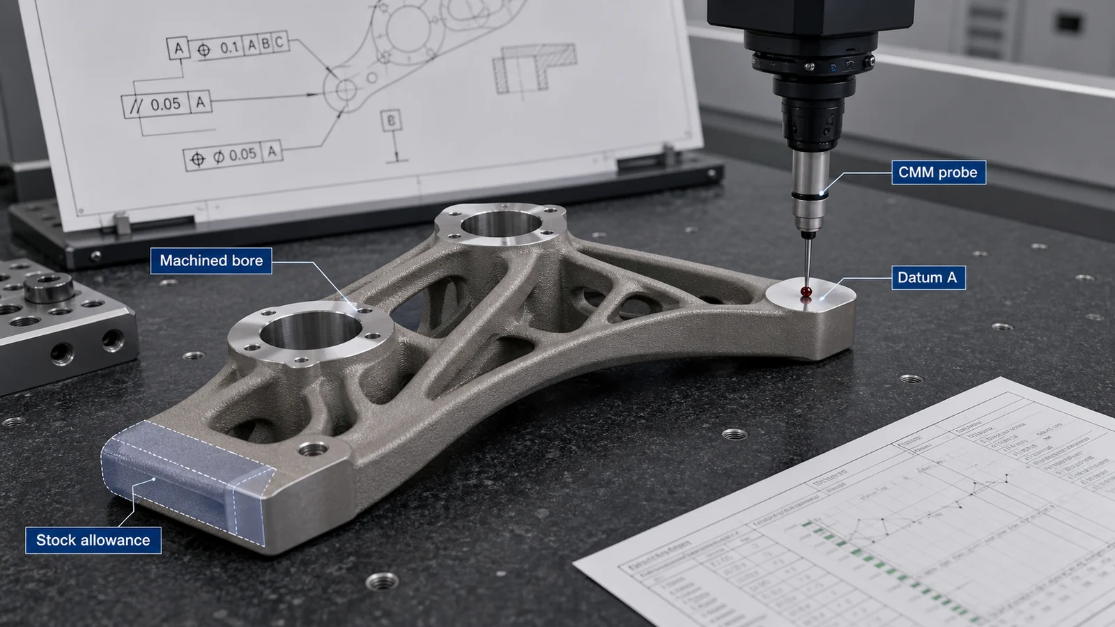
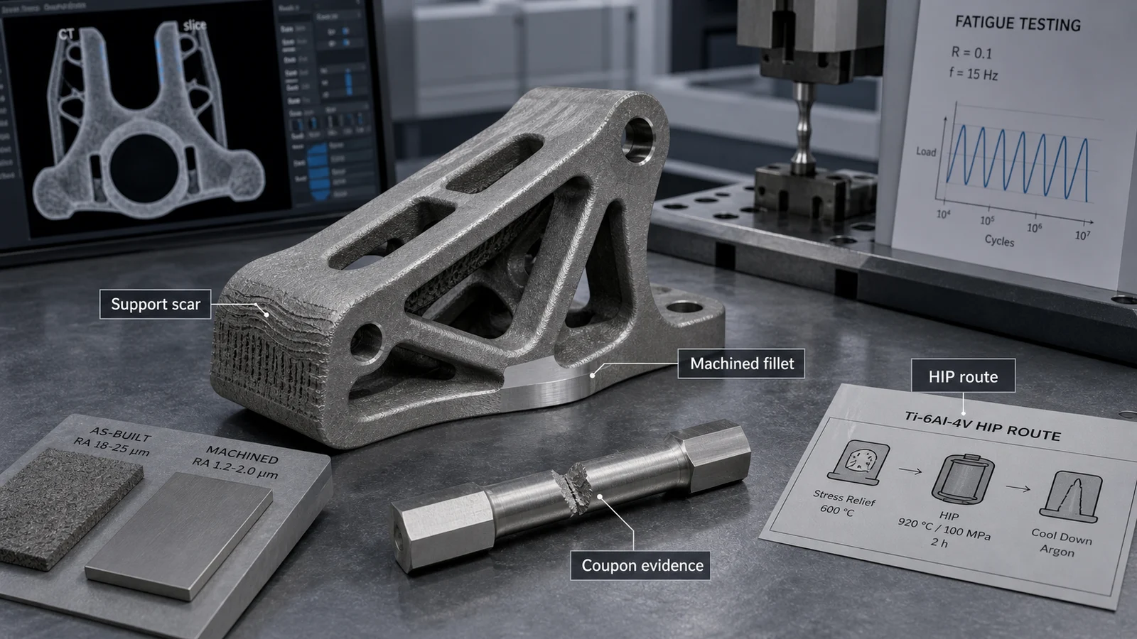
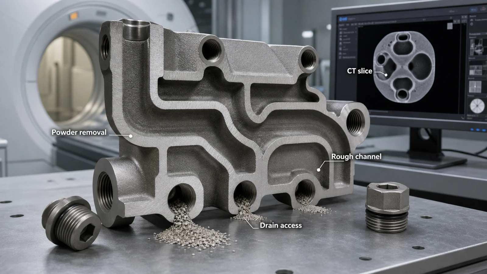
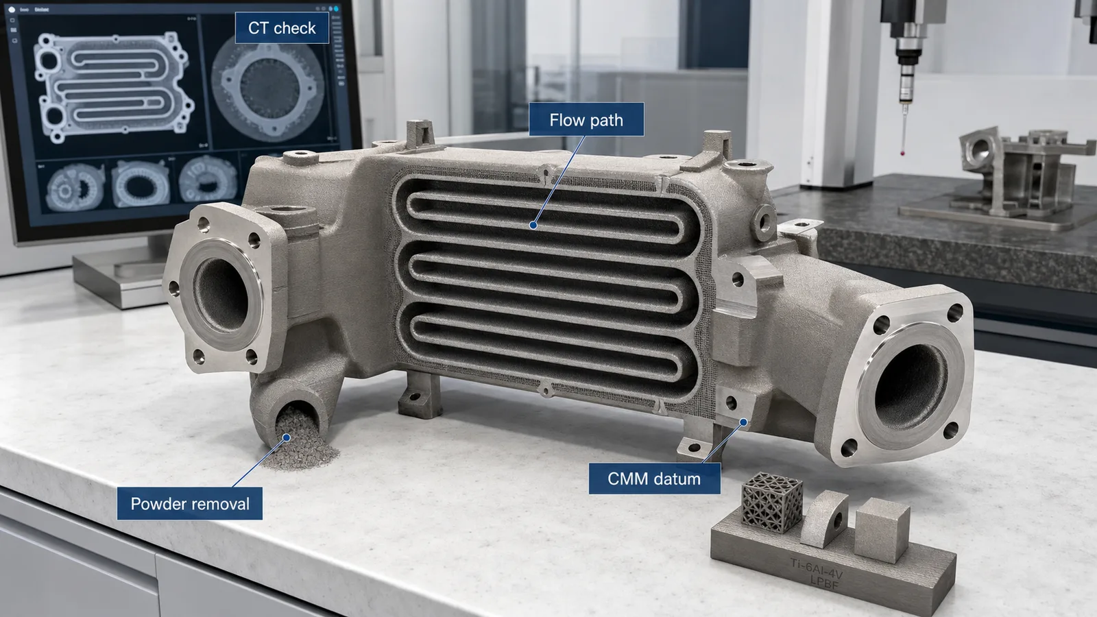
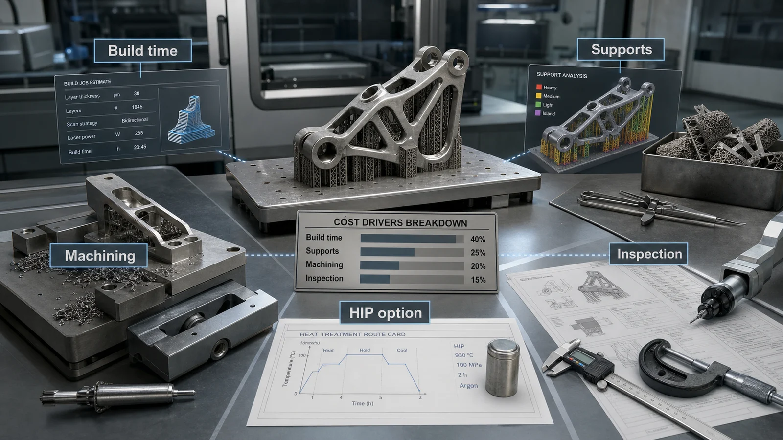
Representative article image; not a customer acceptance record or proof of a qualified manufacturing route. Refer to the cited sources and part-specific inspection records for engineering evidence.
On this page
Titanium 3D printing tolerances are often misunderstood because buyers ask the wrong first question. The useful question is not “What tolerance can AM hold?” The useful question is “Which features must be printed, which features must be machined, which datums control inspection, and what evidence proves the delivered part is acceptable?”
For production RFQs, tolerance planning is a route decision. It affects orientation, support placement, stress relief, machining stock, fixture design, surface finishing, CMM programming, CT scope, and cost. A tight note on the drawing can be cheap or expensive depending on where it lands.
This guide explains how to specify tolerances for titanium AM parts without creating avoidable quote risk.
Quick Answer
For titanium 3D printed parts, separate the tolerance plan into four groups:
- Functional interfaces that should be machined, such as bores, threads, sealing faces, bearing lands, datum pads, and tight assembly surfaces.
- As-built surfaces that can keep the natural AM texture and process-dependent dimensional variation.
- Finished but not precision-machined surfaces that need blasting, polishing, deburring, or cosmetic control.
- Inspection-critical features that need stable datums, CMM access, CT review, gauges, or documented acceptance criteria.
These are routing categories, not universal capability bands. ISO/ASTM 52911-1:2019 provides process-specific design recommendations for laser-based powder bed fusion of metals, while ISO/ASTM 52902:2023 uses measured test artefacts to assess an AM system’s geometric performance. Neither source sets a blanket tolerance for every titanium AM part. A quoted limit should therefore be tied to the alloy, AM process and equipment, orientation, feature geometry, build or post-processed state, surface condition, inspection method, and agreed acceptance rule.
Avoid demanding tight all-over tolerances on as-built titanium AM surfaces. Define the functional surfaces, leave machining stock where needed, define and qualify the thermal, support-removal, and machining sequence, and make the inspection datum scheme match the manufacturing route.
Why Tolerance Questions Break Titanium AM Quotes
Many RFQs send a STEP file and a drawing with a general tolerance block copied from a machined-part template. That can be risky for titanium additive manufacturing because the printed shape, support scars, surface roughness, and post-processing sequence are different from billet machining.
Two suppliers may read the same drawing in different ways:
- One quotes print, support removal, and a basic dimensional check.
- Another quotes stress relief, machining, fixture work, CMM inspection, surface finish, and a document package.
The second quote may look expensive, but it may be the only quote that includes the work required for acceptance. This same scope problem appears in cost comparisons, which is why the Titanium 3D Printing Cost Drivers guide recommends comparing delivered accepted parts, not print-only prices.
Tolerance ambiguity creates risk margin. Suppliers must guess whether the buyer expects an as-built component, a near-net component with selected machining, or a fully finished precision part. Good RFQ wording removes that guesswork.
As-Built Tolerances Are Not the Same as Machined Tolerances
As-built titanium AM surfaces are shaped by powder-bed process physics, build orientation, layer strategy, thermal history, support contact, and local geometry. They are useful for many noncritical surfaces, lightweight structures, housings, brackets, flow bodies, and organic forms. They are not automatically equivalent to machined faces.
Machined surfaces are different because the final geometry is cut after printing and post-processing. If a bore, thread, datum face, sealing land, or sliding interface must assemble predictably, it usually belongs in the machined group.
The practical design decision is to classify every important surface:
| Surface or feature | Typical route | Why it matters |
|---|---|---|
| Bores and bearing seats | Print undersize or with stock, then machine | Roundness, position, and finish are usually functional |
| Threads | Machine or tap after printing | As-built threads can be rough, distorted, or difficult to gauge |
| Sealing faces | Machine or finish by a controlled process | As-built texture may not meet the specified sealing or mating condition |
| Datum pads | Machine after the specified thermal step | CMM and fixture repeatability need stable reference surfaces |
| Noncritical external skins | Leave as-built or blast | Avoid paying to finish surfaces that do not affect function |
| Internal channels | Print as designed, then clean and inspect | Powder removal and access often matter more than cosmetic finish |
This classification keeps precision where it creates value and removes unnecessary work where it does not.
Start With the Manufacturing Sequence
A strong titanium AM tolerance plan follows the actual sequence of work. ISO/ASTM 52908:2023 addresses qualification, quality assurance, post-processing, inspection, and testing for metal powder-bed-fusion parts, but it does not create one universal sequence for every titanium alloy, geometry, or application.
- Review geometry, process choice, orientation, support risk, and powder-removal needs.
- Print with enough stock on functional machining surfaces.
- Apply the specified and qualified thermal treatment at the defined stage; where residual-stress distortion is a concern, review whether stress relief must precede support removal or critical machining.
- Remove supports without damaging critical surfaces.
- Machine primary datums and fixture references.
- Finish bores, threads, sealing faces, contact planes, and critical interfaces.
- Perform CMM, CT, leak, roughness, or other inspection against the defined acceptance plan.
If the drawing treats the printed state and the final machined state as the same thing, the inspection plan becomes confused. If a datum is created during machining, CMM should reference that final machined datum. If a surface is left as-built, the tolerance and inspection method should reflect that condition.
The post-processing sequence is covered more broadly in Post-Processing for Titanium 3D Printing, but the key point is simple: tolerance planning belongs before the quote, not after the first build.
Datum Planning for Titanium AM
Datum planning is where many AM drawings fail. A datum is not just a letter on a drawing. It must be physically stable, reachable by tooling, repeatable in a fixture, and meaningful for the final assembly.
Poor datum choices include:
- Down-facing rough surfaces with heavy stair-step texture.
- Support-scarred areas that will be ground manually.
- Thin flexible walls that move during clamping.
- Internal surfaces that cannot be probed or cleaned reliably.
- Surfaces that are machined away after inspection.
Better datum choices include:
- Machined pads designed for CMM and assembly reference.
- Robust bosses or lands connected to the main load path.
- External planes that remain accessible after support removal.
- Features created after stress relief so inspection matches the final state.
- Datum targets that avoid large rough areas and focus on repeatable contact points.
For titanium AM, it is often useful to add small sacrificial datum pads or machining tabs if they simplify fixturing and inspection. These features should be designed intentionally, not improvised after printing.
GD&T Should Express Function, Not Fear
GD&T can make a titanium AM drawing clearer when it expresses functional relationships. The drawing should name one governing convention and edition: ASME Y14.5-2018 (R2024) establishes rules for stating and interpreting GD&T, while ISO 1101:2017 defines the ISO symbol language and interpretation rules for geometrical specifications. These standards communicate design intent; they do not establish titanium AM process capability or guarantee that a feature is physically inspectable.
GD&T can also make a quote worse when it applies tight controls to every surface without explaining what matters.
Useful GD&T intent might define:
- Position of machined ports relative to primary datum pads.
- Flatness of a sealing face after final machining.
- Perpendicularity of a bore to a mounting face.
- Profile tolerance for a noncritical as-built envelope.
- Datum targets for a rough but acceptable exterior surface.
Weak GD&T intent often looks like blanket profile tolerances over an organic AM surface, tight positional controls on unsupported thin features, or a title-block tolerance scheme that was intended for CNC machining.
The best RFQ posture is to define what must assemble, seal, rotate, locate, or carry load. Then ask the supplier to confirm which features should be printed near-net and which should be finished by machining.
Machining Stock Is a Design Requirement
If a feature will be machined, the printed part needs stock. Without stock, the machinist may have no material left to clean up roughness, correct distortion, or establish a final datum.
There is no universal machining-stock value in this guide. The allowance should be proposed and substantiated for the selected equipment, orientation, local geometry, support condition, thermal route, fixture strategy, cutter access, and final acceptance requirement.
Machining stock should be planned around:
- Support contact and support-removal marks.
- Down-facing roughness.
- Expected distortion after stress relief and plate removal.
- Tool access and cutter clearance.
- Clamp access and fixture stability.
- Final surface finish and dimensional acceptance.
Do not add stock everywhere by default. Excess stock increases print time, machining time, and distortion risk. Add stock where the final function needs it: bores, threads, sealing faces, datum pads, bearing surfaces, and other controlled interfaces.
This is closely tied to DfAM. The Titanium DfAM Rules for LPBF and EBM article explains why supports, overhangs, thin walls, powder removal, and machining access need review before the build plan is frozen.
CMM Inspection Needs a Route-Aware Drawing
CMM inspection is valuable only when the drawing and route make the measurement meaningful. A CMM report that references unstable or inaccessible datums can create false confidence or unnecessary rejection.
ISO 10360-2:2009 addresses acceptance and reverification of Cartesian CMM performance using contact probes in discrete-point mode; its official scope does not explicitly cover optical or non-Cartesian systems. That machine-performance standard does not by itself establish whether a specific titanium AM part conforms. The contract still needs feature-level criteria, datum alignment, measurement strategy, sampling if applicable, and an agreed treatment of measurement uncertainty and acceptance decisions.
Before requesting CMM, define:
- Which drawing and GD&T standard edition governs interpretation.
- Which datums are final datums.
- Whether datums are as-built, machined, or fixture-derived.
- Which dimensions are critical to assembly or function.
- Whether surface finish affects probing.
- Whether flexible regions need special fixturing or restrained-state inspection.
- Whether CMM should occur before or after final finishing.
- Which uncertainty or decision rule applies when a result is near a tolerance limit.
For a simple prototype, a limited dimensional report may be enough if the customer defines that acceptance scope. For a production assembly component, CMM may need to cover datum pads, port positions, bore axes, sealing faces, and mounting interfaces. NIST’s AM Part Qualification project identifies complex surfaces, internal geometry, internal defects, and anisotropic properties as distinct measurement challenges and investigates multiple post-process metrology and NDT methods. A CMM report therefore does not prove unmeasured internal geometry, defect acceptance, or material integrity; CT, NDT, or functional tests may be needed under a separate, defined acceptance plan. The broader evidence framework is in Titanium AM Qualification and Inspection Evidence.
Tolerance Planning for Common Features
Different features need different routes. Treating them all the same is one of the fastest ways to create an expensive or unbuildable RFQ.
The routes below are review heuristics, not universal dimensional capabilities, design allowables, or acceptance criteria. ISO/ASTM 52901:2017 calls for the customer and part provider to exchange part-definition, final-characteristic, inspection, and acceptance information at the time of order. The drawing, purchase order, applicable material and industry specifications, and supplier evidence for the selected route remain controlling.
Bores
Critical bores are often candidates to be printed undersize or near-net and then machined, but the supplier should confirm the route against stock, distortion, tool access, and demonstrated capability. The drawing should define final diameter, position, axis relationship, surface finish if needed, and inspection method. If the bore is deep or blocked by surrounding geometry, tool access must be reviewed before quoting.
Threads
Threads are commonly added after printing by tapping, thread milling, inserts, or another controlled route. Treat an as-built printed thread as a process-specific option, not an assumed capability: the drawing should define the interface, load or retention function, assembly-cycle needs, surface condition, gauging method, and acceptance criteria, and the supplier should provide route-specific evidence.
Sealing Faces
Sealing faces need more than a nominal flat surface. Depending on the joint design and governing specification, they may require flatness, surface texture, scratch or damage limits, leak testing, and a defined mating, gasket, or seal condition. If the sealing face is down-facing or support-contacted, machining stock and support avoidance should be planned early.
Datum Pads
Datum pads should be accessible, robust, and connected to the functional geometry. A small machined datum pad can simplify fixture setup, CMM programming, and assembly inspection. It can also reduce cost by avoiding over-inspection of rough surfaces.
Thin Walls and Long Plates
Thin titanium AM features can move during stress relief, support removal, machining, and inspection. Tight tolerances on long thin walls need a restraint plan, a realistic inspection state, or a design change. If a thin wall is nonfunctional, relax the requirement instead of forcing the supplier to chase distortion.
Internal Channels
CMM cannot inspect most internal flow paths. Internal channels require design for powder removal and cleaning access, plus CT, flow, pressure, or another inspection or functional method when required by the design authority and applicable specification.
CT does not have one universal detection or dimensional-capability threshold. A NIST review of CT dimensional traceability frames measurement confidence through calibration, traceability, and quantitative uncertainty; a separate NIST study of AM lattice measurement explains why rough surfaces and form deviations can complicate similarity-based CT uncertainty assessment. A CT purchase scope should therefore identify the target dimension or indication, relevant material and section geometry, calibration or reference approach, required uncertainty or probability of detection where applicable, and the acceptance rule. That topic is covered in detail in Titanium 3D Printed Internal Channels: Powder Removal and CT.
A Hypothetical RFQ Scenario
Consider a Ti-6Al-4V hydraulic manifold with internal passages, four threaded ports, a gasket face, two mounting bosses, and organic weight-reduction geometry.
This is a hypothetical procurement-scope example. It is not a customer case, a validated pressure design, a qualified production route, or evidence of any supplier certification or site capability.
For a deeper fluid-power RFQ route covering valve ports, leak testing, pressure testing, CT, and cleaning, use Titanium 3D Printing for Hydraulic Manifolds and Fluid Power Components.
A weak drawing says:
Print in titanium. General tolerance applies. Inspect before shipment.
This leaves the supplier to guess whether ports are printed or machined, whether the gasket face is sealed as-built or finished, which surface controls the CMM report, whether internal channels need CT, and whether supports can touch the mounting bosses.
A stronger drawing says:
Quote a delivered Ti-6Al-4V part. Internal channels are functional and require powder-removal review. Port threads, gasket face, mounting bosses, and datum pads are final machined features. Noncritical external lattice and body surfaces may remain as-built after support removal and cleaning. CMM report should reference machined datum pads A, B, and C. Please identify required machining stock, orientation concerns, CT scope for channels, and any geometry changes that reduce support contact on functional surfaces.
The second version is easier to quote, build, and inspect because it exposes the required route decisions. It does not establish a pressure rating, leak or burst acceptance, fatigue life, cleanliness requirement, or regulatory approval.
For critical metal PBF applications, ISO/ASTM 52904:2024 covers machine and process operation and production control, while explicitly leaving field-specific requirements to the relevant application standards. NASA-STD-6030 is one demanding example for NASA spaceflight hardware; its scope does not automatically apply to, or qualify, a commercial hydraulic component.
Cost Trade-Offs: Where to Spend and Where Not To
Tolerance planning is also cost planning. Spend on features that control function. Avoid spending on surfaces that only look precise on paper.
Good places to spend:
- Machined datum pads for repeatable CMM and assembly.
- Machining stock around ports, bores, threads, and sealing faces.
- A qualified thermal, support-removal, and machining sequence where distortion affects critical features.
- CMM reporting for assembly-critical geometry.
- CT or functional testing when internal features affect acceptance and the method has a defined scope and decision rule.
- Surface finishing where fatigue, sealing, friction, or flow requires it.
If the tight feature is also fatigue-critical, review Titanium 3D Printing Fatigue Design before deciding whether machining, polishing, HIP, CT, or coupons belong in the route.
Common waste:
- Tight all-over tolerances on nonfunctional as-built skins.
- Cosmetic finishing on hidden or irrelevant surfaces.
- CMM reporting on dimensions that do not affect approval.
- Datums placed on rough, flexible, or manually finished regions.
- Printed threads specified without a functional reason.
- CT scans requested with no target indication, uncertainty or detection requirement, or decision rule.
The goal is not to avoid precision. The goal is to buy the precision that the part actually needs.
RFQ Checklist for Toleranced Titanium AM Parts
Send these inputs when asking for a production-ready quote:
- STEP file and 2D drawing.
- Alloy grade, such as Ti-6Al-4V, Ti-6Al-4V ELI, or CP titanium.
- Governing drawing or GD&T standard and edition, units, and the scope of any general tolerance note.
- Applicable material, process, industry, or regulatory specifications and revision levels, identifying which are mandatory.
- Required process if fixed, or permission to recommend LPBF, EBM, DED, machining, or a hybrid route.
- Quantity, target lead time, and expected repeat volume.
- Critical surfaces, bores, threads, sealing faces, and assembly interfaces.
- Datum scheme and whether final datums are machined or as-built.
- Surfaces that may remain as-built.
- Surfaces requiring machining, finishing, or roughness control.
- Machining stock expectations or permission for supplier recommendation.
- CMM scope, CT scope, leak test, functional test, coupons, and documentation needs.
- Acceptance method for each critical characteristic, including uncertainty or decision rules where contractually required.
- Required COA, COC, traceability, build records, or inspection reports.
The Titanium AM RFQ and Procurement Guide provides a broader purchasing checklist for comparing suppliers on the same delivered scope.
Better Tolerance Wording
Weak wording:
All dimensions must meet tight tolerance after titanium 3D printing.
Better wording:
Please quote a delivered Ti-6Al-4V part. Critical features are the machined datum pads, four port bores, port threads, mounting bosses, and sealing face. External noncritical surfaces may remain as-built after support removal and cleaning. Please propose machining stock, orientation, support strategy, CMM datum scheme, and inspection scope required to meet the final drawing.
This wording helps the supplier quote the real route instead of guessing whether every surface needs precision finishing.
When Titanium AM May Be the Wrong Route
If the part is mostly simple prismatic geometry with tight tolerances on many faces, conventional machining may be better. Titanium AM is strongest when it creates value through internal channels, weight reduction, part consolidation, complex load paths, or geometry that is difficult to machine from billet.
If the only requirement is a tight block, plate, shaft, or simple bracket, AM may add post-processing and inspection cost without adding functional value. The screening logic is covered in When Not to Use Titanium Additive Manufacturing.
Bottom Line
Titanium 3D printing tolerances should be specified around the delivered route, not the printed shape alone. Define which features remain as-built, which features are machined, which datums control inspection, and which evidence proves acceptance.
The practical engineering answer is to avoid vague precision everywhere. Ask for controlled precision where the part assembles, seals, locates, carries load, or passes inspection.
No standard link, CMM report, CT scan, or process description by itself proves that a supplier is certified or that a submitted part is qualified. Acceptance must come from the governing drawing and purchase order, applicable specifications, a qualified supplier route, and part- or lot-specific evidence agreed by the customer and supplier.
Official Sources and Scope
- ISO/ASTM 52911-1:2019 — Design for laser-based powder bed fusion of metals: process-specific design recommendations. It does not publish one universal titanium tolerance.
- ISO/ASTM 52902:2023 — Test artefacts for AM system geometric capability: measured artefacts for capability evaluation and calibration. A system benchmark is not automatic acceptance of a production part.
- ISO/ASTM 52901:2017 — Requirements for purchased AM parts: customer-provider information exchange, final-part characteristics, inspection, and acceptance at order stage. More stringent or application-specific requirements still need to be stated.
- ISO/ASTM 52908:2023 — Post-processing, inspection, and testing of metal PBF parts: qualification and quality-assurance framework for defined quality levels. It does not prescribe one fixed route for every titanium part.
- ASME Y14.5-2018 (R2024) and ISO 1101:2017: official GD&T/GPS language and interpretation sources. They communicate requirements but do not prove manufacturing or measurement capability.
- ISO 10360-2:2009 — CMM acceptance and reverification: performance verification for the stated Cartesian contact-probing scope. It is not a part-specific qualification or internal-defect standard.
- NIST Additive Manufacturing Part Qualification and NIST CT dimensional-traceability review: primary measurement-science sources for AM geometry, defect, metrology, traceability, and uncertainty challenges. They do not provide a supplier-specific CT detection guarantee.
- ISO/ASTM 52904:2024 — Metal PBF for critical applications and NASA-STD-6030 — Additive Manufacturing Requirements for Spaceflight Systems: critical-application control references. NASA-STD-6030 is limited to NASA spaceflight hardware, and neither source replaces the governing sector, product, pressure-system, or regulatory requirements.
- Tolerances
- Datum planning
- CMM
- Machining
- DFAM
- RFQ
- Inspection
- LPBF