· Updated - TITANIUM 3DP Engineering - Engineering Guides - 9 min read
Titanium DfAM Rules: Supports, Overhangs, Thin Walls, and Powder Removal
Design titanium LPBF and EBM parts around support access, down-skin surfaces, thin-wall distortion, powder removal, machining datums, fatigue surfaces, and measurable acceptance.
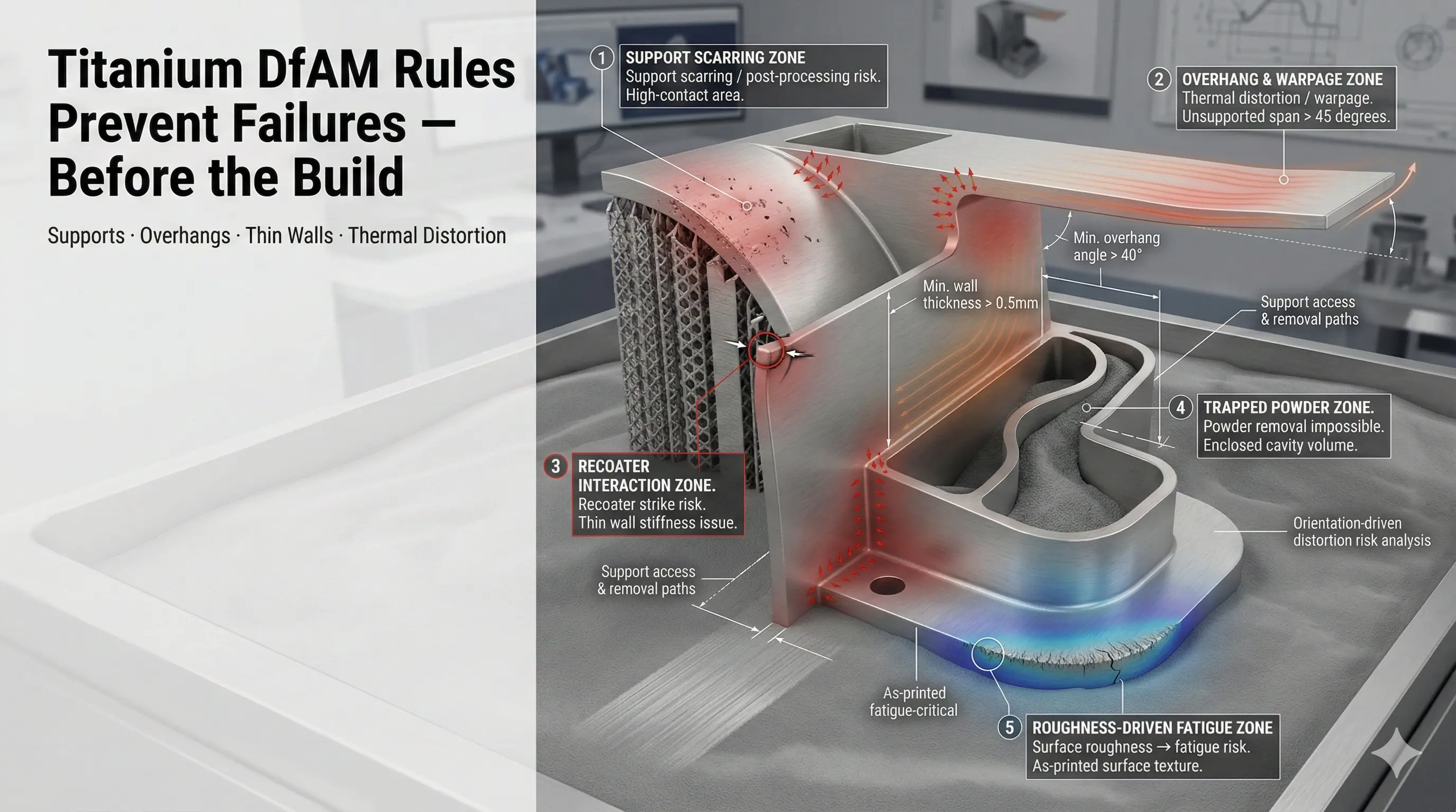
Representative article image; not a customer acceptance record or proof of a qualified manufacturing route. Refer to the cited sources and part-specific inspection records for engineering evidence.
On this page
Titanium DfAM is the work of converting a functional CAD model into a part that can be built, depowdered, separated, heat treated, machined, inspected, and accepted. A geometry is not production-ready merely because a supplier can place it in a build volume or generate supports.
The important rules are connected. Orientation changes support contact, down-skin quality, build height, thermal behavior, distortion, and mechanical-property direction. Those choices change support removal, machining access, CT visibility, surface finishing, cost, and the evidence needed at release.
Short Answer
Before requesting a titanium LPBF or EBM quote, identify:
- Surfaces that must not receive supports.
- Features that may be machined and the stock/tool access they require.
- Thin or long features vulnerable to distortion.
- Down-facing and fatigue-sensitive surfaces that need a controlled finish.
- Cavities, lattices, and channels that require powder exits and inspection access.
- Datums that exist at the correct stage of the manufacturing route.
- Acceptance criteria that can be measured after all post-processing.
Do not publish or purchase around a universal minimum wall, hole, overhang, or tolerance. Feasibility depends on the selected process, machine, parameter set, alloy, layer strategy, orientation, local heat flow, geometry scale, support method, post-processing, and supplier evidence. Ask for a part-specific capability response.
If the manufacturing route is still open, use the titanium AM process-selection guide before applying LPBF or EBM design assumptions.
DfAM Decision Table
| Geometry decision | Why it matters | Supplier question | Evidence or drawing output |
|---|---|---|---|
| Build orientation | Changes support area, down-skin condition, build height, distortion, and directional evidence | Which orientation is proposed, and what assumptions change if it moves? | Controlled orientation or supplier-approved range for production-intent work |
| Support contact | Can damage datums, seals, fatigue surfaces, and inaccessible features | Where will supports touch, and how will they be removed? | No-support zones, removal route, machining or finishing allowance |
| Thin walls and long spans | Local thermal imbalance can move geometry or create unstable sections | Which features require thickening, ribs, segmentation, or a route change? | Supplier capability response and inspection plan tied to the actual feature |
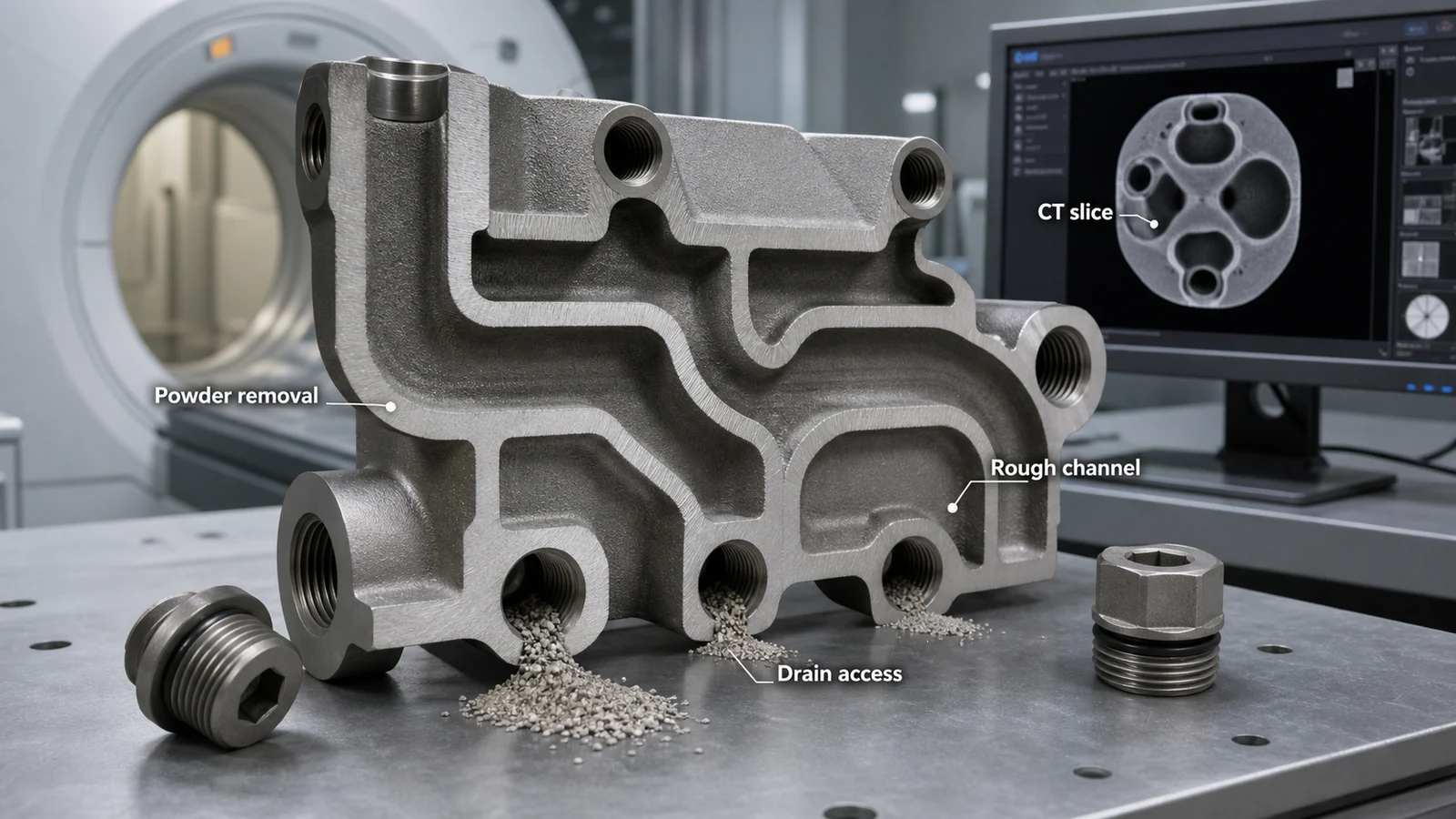
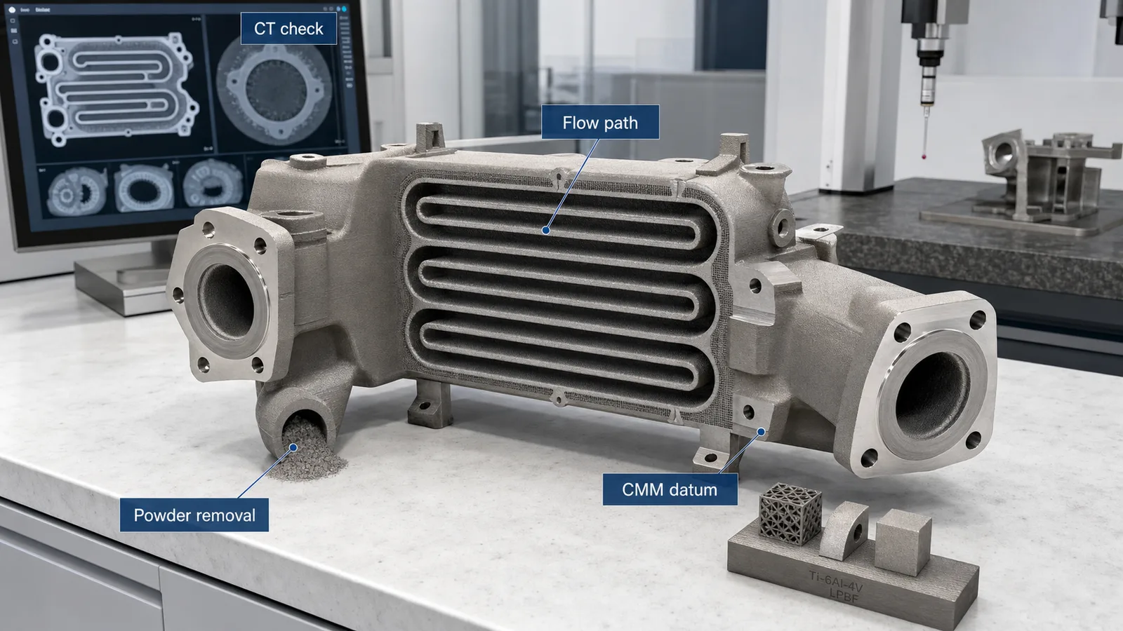
| Internal channels and lattices | Powder, residue, roughness, blockage, and hidden defects can remain inaccessible | How will powder exit, cleaning be verified, and internal geometry be accepted? | Drain/exit strategy, CT/flow/leak criteria, cleaning route |
| Machined interfaces | Printing alone may not achieve the datum, seal, bore, thread, or contact requirement | Is stock present, is the tool path open, and when are datums created? | Finished-state drawing, setup datums, machining stock, CMM scope |
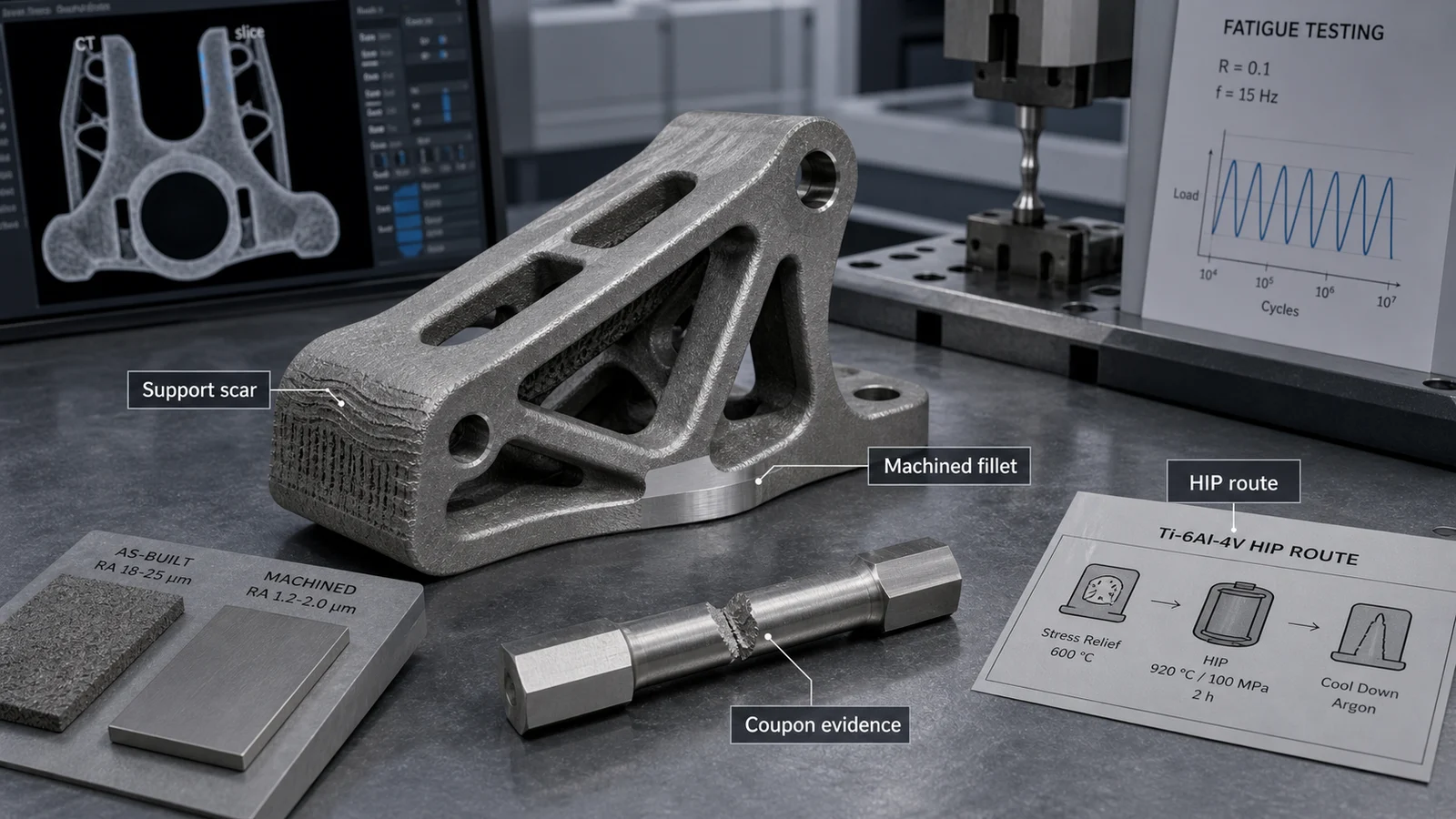
| Fatigue surfaces | Support scars, notches, roughness, defects, and orientation can dominate life | Which surfaces control fatigue, and what is their final state? | Surface zones, post-process route, coupon/test basis, inspection scope |
The table should produce design changes or controlled assumptions, not a generic “printable” approval.
Start With the Manufacturing Sequence
A useful DfAM review follows the intended process chain:
- Receive and control CAD/drawing revisions.
- Select process, orientation, support concept, and build layout.
- Build and depowder while the part is still in the planned restraint condition.
- Apply the specified thermal route at the required stage.
- Separate from the plate and remove supports without damaging protected zones.
- Establish machining datums, finish functional features, and apply surface treatments.
- Clean, inspect, test, document, and release the delivered part.
The post-processing guide for titanium 3D printing covers those downstream operations. DfAM should reserve the access, stock, fixtures, and inspection features they require.
Build Orientation Is a Controlled Trade-Off
There is rarely one orientation that minimizes every risk. A low build height may increase support contact on a critical face. Rotating a bore may improve support access but change its as-built form and machining setup. Aligning a load path with one build direction can make another surface harder to finish or inspect.
Ask the supplier to compare orientation against:
- Critical-face and down-skin condition.
- Support volume, contact zones, and removal access.
- Build height and schedule/cost implications.
- Thermal mass transitions and distortion risk.
- Powder evacuation from internal features.
- Machining setups and stable datum creation.
- Directional material or coupon evidence required by the project.
- CT, CMM, roughness, leak, or flow access after the build.
For production-intent parts, a material or process change is not the only change that can affect the evidence basis. An orientation change can alter surface state, support scars, dimensional behavior, and the relevance of test coupons. Put the approval route for that change in the quality plan.
Protect Functional and Fatigue-Sensitive Surfaces
Mark surfaces by function rather than by appearance:
- Datum and contact surfaces.
- Sealing lands and gasket faces.
- Bearing bores, threads, and precision ports.
- Fatigue-critical radii and load-transfer transitions.
- Sliding, wear, thermal-contact, or fluid-wetted surfaces.
- Areas that must remain free of support contact or loose powder.
If support contact cannot be avoided, define what happens next. Machining, grinding, polishing, or another controlled process may be needed. The design must include material allowance and tool access; the drawing must state the final surface and dimensional requirement.
Support scars are not only cosmetic. They can create local roughness, geometric ambiguity, and notch-like features. HIP does not remove a support scar or machine a sealing face. For cyclic parts, connect the support plan to the titanium AM fatigue guide before releasing the geometry.
Overhangs and Down-Skin Surfaces Need Supplier Evidence
Overhang behavior is local. The result depends on the angle and span, but also on heat flow, section thickness, nearby mass, scan strategy, material, process, and orientation. A generic angle copied from a design poster is not a production acceptance limit.
During review, classify an overhang as one of four cases:
- Self-supporting under the supplier’s controlled route.
- Supported and accessible for removal.
- Supported, then machined or finished to the final requirement.
- Not defensible; redesign the geometry or change the process.
For down-facing functional surfaces, specify the final state and the way it will be checked. “As printed” is a manufacturing condition, not an acceptance criterion.
ISO/ASTM 52911-1:2019, confirmed current by ISO in 2026, gives detailed design recommendations for laser-based powder bed fusion of metals. Its public scope also notes that some principles can apply to other AM processes only when process-specific features are considered. That is why LPBF guidance should not be copied into an EBM or DED quote without supplier review.
Thin Walls, Long Features, and Section Transitions
Thin walls become difficult when their behavior is coupled to geometry around them. A wall connected to a thick boss, a long plate restrained at one edge, or a fine rib crossing a heavy section may experience a different thermal and separation history from a small test coupon.
Review:
- Wall height, unsupported length, curvature, and local restraint.
- Connection to thick bosses, flanges, and heat-concentrating sections.
- Whether the wall is structural, sealing, sacrificial, or only a machining blank.
- Support-removal force and fixture access.
- Plate-separation and stress-relief sequence.
- CMM or other measurement access without deflecting the feature.
- Whether a representative feature coupon or trial build is needed.
If a supplier gives a minimum dimension, record it as a machine/material/orientation-specific capability window and ask what evidence supports it. Do not turn it into a universal site claim or drawing rule.
Powder Removal and Cleaning Must Be Designed In
Internal channels, hollow bodies, and lattices can create the strongest AM value and the largest acceptance risk. Every enclosed volume needs a deliberate answer for powder exit, access, cleaning, inspection, and final closure if an access feature is later sealed.
High-risk patterns include:
- Blind pockets and dead-end branches.
- Long tortuous paths with no line of sight or effective agitation route.
- Fine lattices that retain powder or cleaning residue.
- Cross-sections that trap powder at orientation-dependent low points.
- Access holes that cannot later be machined, plugged, welded, or inspected as required.
- Channels whose CT or flow-test requirement exceeds the proposed inspection capability.
For functional flow paths, define media, pressure/temperature duty, allowable blockage, flow or pressure-drop basis, cleaning method, leak or proof test, and the role of CT. The internal-channel, powder-removal, and CT guide develops that acceptance path in detail.
Design Machining and Inspection Together
Critical bores, threads, seals, flatness faces, and alignment features commonly need machining. The design should answer:
- What stock remains after support removal and thermal processing?
- Can the tool and fixture reach the feature?
- Which surfaces establish the first stable machining datum?
- Does the datum exist before or after plate separation?
- Can CMM or another method verify the finished feature from the same datum scheme?
- Are internal or hidden features visible to the chosen inspection method?
The titanium AM tolerance and datum guide shows how to separate as-built, intermediate, and finished-state requirements. This separation prevents a supplier from pricing a print-only shape against a drawing that actually demands a machined component.
Common Titanium DfAM Failure Modes
A critical seal face is used as a support landing. The print is possible, but the delivered finish and flatness route were never priced.
A channel has no verifiable depowdering route. Shaking powder out is treated as acceptance even though blockage, residue, and cleanliness remain unknown.
A thin feature passes a coupon rule but distorts in the actual part. Local thermal mass, restraint, and separation sequence were not represented.
Machining stock exists but tool access does not. The supplier must add setups, redesign the fixture, or reopen CAD after quotation.
HIP is used as a substitute for design control. Geometry, support scars, surface-connected defects, trapped powder, and inaccessible finish remain unresolved.
Orientation changes without change control. The part keeps the same drawing revision while support, surface, dimensional, and coupon assumptions move.
Inspection is specified after the geometry is frozen. CT resolution, CMM access, datum stability, or flow-test ports cannot support the intended acceptance decision.
Titanium DfAM RFQ Checklist
Include:
- Controlled STEP/native CAD and a drawing with revision, units, and authority.
- Material grade, applicable component specification, and open or fixed process route.
- Quantity, lot intent, prototype/production status, and target delivery.
- Load path, fatigue-sensitive zones, pressure/flow duty, temperature, and media.
- Critical datums, seals, bores, threads, ports, contact faces, and keep-out zones.
- Surfaces where supports are prohibited or controlled finishing is required.
- Internal volumes, powder exits, cleaning route, and closure of access features.
- Proposed machining stock, tool access, fixtures, and datum sequence.
- Required thermal processing, HIP if justified, surface finish, and cleaning.
- CMM, CT, roughness, coupons, leak/flow tests, and documentation tied to acceptance.
- Supplier output: proposed orientation, support concept, exceptions, redesign requests, process assumptions, and cost/schedule effects.
Use the titanium 3D printing cost guide to price these decisions as one delivered route, then send the controlled package through the titanium AM RFQ checklist.
Sources and Scope
This guide uses the public scope of ISO/ASTM 52911-1:2019 for laser-based metal powder bed fusion design and the purchasing context of ASTM F2924-14(2021) for Ti-6Al-4V full-melt powder bed fusion components. NIST’s Additive Manufacturing Part Qualification project explains why complex geometry, surface topography, internal defects, residual stress, anisotropy, and post-processing create measurement and qualification challenges.
These sources support a risk-based design and evidence framework. They do not provide universal feature limits for every titanium machine, alloy, parameter set, orientation, or supplier. Confirm the current standard revision and obtain the supplier’s documented capability for the actual geometry.
The correct DfAM output is not “printable.” It is a controlled route from CAD to an inspectable, cleanable, machinable, and acceptable titanium part.
- DFAM
- LPBF
- EBM
- Supports
- Overhangs
- Thin walls
- Fatigue