· Updated - TITANIUM 3DP Engineering - Engineering Guides - 15 min read
Titanium 3D Printing for Hydraulic Manifolds and Fluid Power Components
Engineering RFQ guide for titanium 3D printed hydraulic manifolds and fluid power components, covering valve blocks, actuator manifolds, internal channels, pressure drop, leak testing, CT, CMM, machining, and traceability.
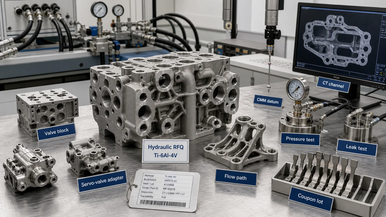
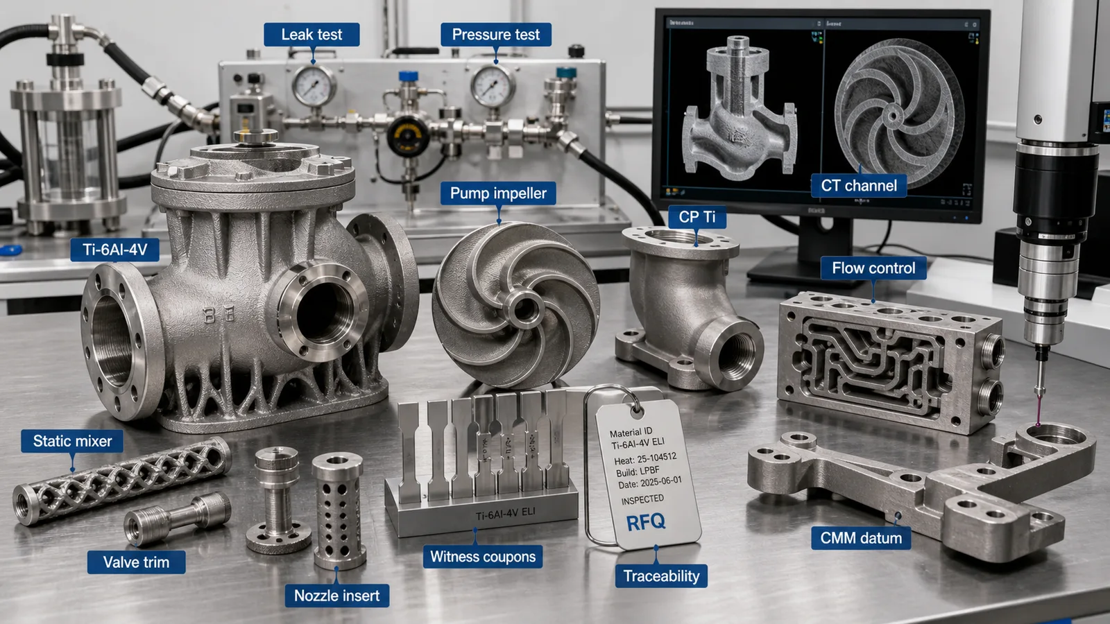
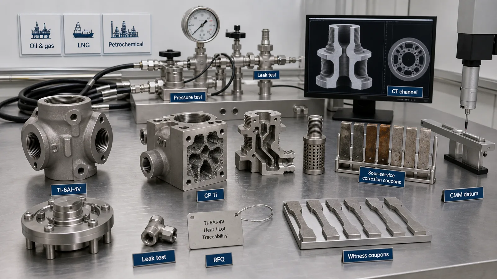
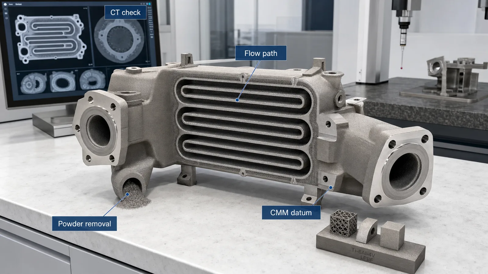
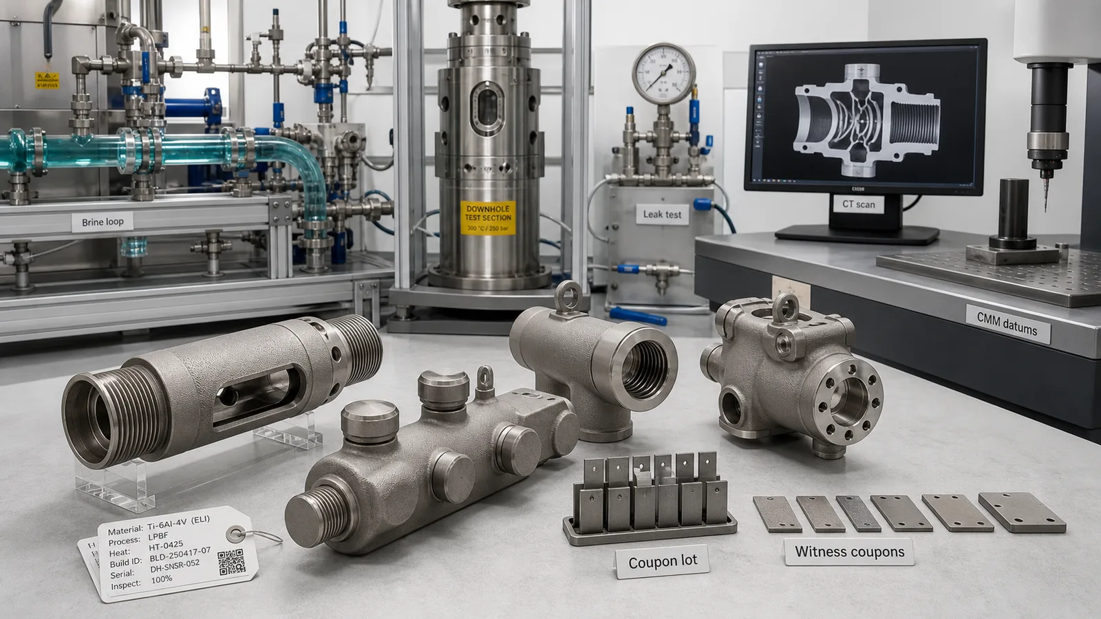
Representative article image; not a customer acceptance record or proof of a qualified manufacturing route. Refer to the cited sources and part-specific inspection records for engineering evidence.
On this page
Titanium 3D printing for hydraulic manifolds and fluid power components is worth reviewing when a valve block, actuator manifold, pneumatic manifold, coolant or oil routing body, or pressure-tested adapter needs compact routing, lower mass, fewer fittings, corrosion resistance, or faster low-volume iteration. It is not a shortcut around hydraulic design, pressure integrity, cleanliness, seal quality, or inspection evidence.
The useful question is not “Can a hydraulic manifold be printed?” The useful question is “Can this titanium AM route deliver a clean, leak-tested, machined, inspected, traceable fluid-power component that is better than the drilled, plugged, brazed, or assembled alternative?”
This guide is written for engineering and procurement teams comparing titanium additive manufacturing for valve blocks, actuator manifolds, compact hydraulic manifolds, pneumatic manifolds, servo-valve adapters, pump interfaces, test-rig blocks, and fluid-power hardware used in aerospace, robotics, marine, motorsport, energy, and industrial equipment.
For industrial process valve bodies, pump adapters, static mixers, nozzles, and corrosion-exposed flow-control hardware beyond hydraulic circuits, use Titanium 3D Printing for Industrial Valves, Pump Parts, and Flow Control Hardware.
Quick Answer
Titanium additive manufacturing can make sense for hydraulic manifolds and fluid power components when the part is compact, high-value, interface-heavy, and difficult to make by conventional drilling, plugging, welding, or assembly.
Strong candidates include:
- Ti-6Al-4V hydraulic manifolds with curved internal channels that replace cross-drilled passages and plugs.
- Actuator valve blocks where lower mass, shorter flow paths, and fewer fittings improve packaging.
- Compact pneumatic or vacuum manifolds for robotics and end-of-arm tooling.
- Aerospace or eVTOL fluid-power adapters where machined ports, leak testing, and traceability are required.
- Marine and subsea hydraulic or seawater manifolds where titanium corrosion resistance and fewer leak paths matter.
- Motorsport coolant, oil, or pneumatic manifolds where packaging space is tight and iteration speed matters.
- Development test blocks, pressure-test fixtures, and pilot hardware where low-volume production is more important than tooling cost.
Weak candidates include commodity hydraulic blocks, large simple manifolds that machine cheaply from aluminum or steel, high-volume catalog valve bodies, safety-critical pressure parts without a qualification plan, and any hidden-channel design that cannot be depowdered, cleaned, inspected, or pressure tested.
If the geometry is mostly a simple rectangular drilled block, start with conventional machining. If the value comes from internal routing, assembly reduction, mass reduction, corrosion resistance, or short-run traceable hardware, titanium AM deserves a structured RFQ.
Why Hydraulic Manifolds and Fluid Power Are Timely
Fluid-power hardware is not a narrow old-industry niche. Compact hydraulic, pneumatic, vacuum, coolant, and fuel-adjacent routing appears wherever machines need force, motion, thermal control, or test infrastructure inside tight packaging.
Recent public signals explain why buyers are revisiting compact, traceable, low-volume fluid hardware:
- The International Federation of Robotics World Robotics reports track industrial, service, and mobile robot growth, which keeps attention on compact end-of-arm tooling, pneumatic manifolds, actuator packaging, and factory automation hardware.
- The FAA describes Advanced Air Mobility aircraft as typically automated, electrically powered, and capable of vertical takeoff and landing, while NASA’s AAM work covers electric air taxis, drones, cargo delivery, and public-service use cases. Those platforms create pressure for compact, lightweight, documented hardware around actuators, cooling, testing, and ground support.
- Naval, offshore, and unmanned maritime programs keep attention on corrosion-resistant routing hardware. For example, the U.S. Navy has publicly discussed MUSV marketplace at-sea demonstrations, a context where autonomy, seawater exposure, and maintainability make compact hardware more interesting.
- Research on AM hydraulic manifolds continues to focus on the same practical issues buyers face: internal channel layout, flow resistance, surface quality, pressure loss, and manufacturability. A 2024 ICAS paper on SLM aircraft hydraulic manifolds discusses channel arrangement and aircraft hydraulic manifold optimization, while an Applied Sciences paper on LPBF manifolds and fluid components frames development workflow around manufacturability and functional performance.
None of these trends mean titanium AM is automatically right. They explain why more teams are asking for compact, lightweight, corrosion-resistant, inspectable fluid-power hardware instead of another heavy drilled block with many plugs and external fittings.
Where Titanium AM Fits in Fluid-Power Hardware
Titanium AM is strongest when the fluid-power component is also a packaging, mass, corrosion, or evidence problem.
| Component family | Why titanium AM can help | Main RFQ risk | Evidence to define |
|---|---|---|---|
| Hydraulic valve block | Curved flow paths, fewer plugs, lower mass | Powder removal, seal faces, pressure cycling | CT or flow check, pressure/leak test, CMM |
| Actuator manifold | Compact routing near moving hardware | Bearing, seal, and port interface accuracy | Machining stock, CMM, leak test |
| Pneumatic or vacuum manifold | Fewer tubes and fittings on robot tooling | Hidden powder or leakage | Cleaning route, leak test, CT if needed |
| Servo-valve adapter | Shorter routing and custom interface geometry | Threaded ports and flatness | Machined threads, seal finish, CMM |
| Marine hydraulic block | Titanium corrosion resistance and fewer joints | Galvanic contact, seawater or hydraulic exposure | Alloy choice, isolation plan, pressure test |
| Motorsport oil or coolant manifold | Tight packaging and fast iteration | Cleaning, leak paths, rulebook fit | Pressure/leak test, revision control |
| Test fixture or pilot block | Low-volume custom routing with traceability | Over-specifying a development tool | Fit check, material record, targeted inspection |
The delivered part should be quoted as a route: print, stress relieve, depowder, machine, clean, inspect, test, document, and package. A print-only quote is not enough for a pressure-carrying or leak-sensitive component.
Start With Fluid, Pressure, Duty, and Acceptance
A hydraulic manifold RFQ should start with the operating map, not the CAD model alone.
Define:
- Fluid type: hydraulic oil, Skydrol-like aviation fluid, water-glycol, air, nitrogen, coolant, seawater, brine, process fluid, or test medium.
- Working pressure, proof pressure, burst requirement if any, hold time, and pressure-cycle expectation.
- Flow rate, acceptable pressure drop, transient events, and temperature range.
- Leak requirement: no visible leakage, pressure decay limit, helium leak rate, bubble test, vacuum hold, or project-specific method.
- Cleanliness requirement: particle limit, cleaning method, flushing, drying, packaging, and whether trapped powder is unacceptable by definition.
- Critical interfaces: cartridge valve bores, threaded ports, O-ring grooves, gasket faces, tube-fitting seats, flanges, bolt patterns, datum pads, and mounting bosses.
- Acceptance evidence: CT, borescope, flow test, pressure test, leak test, CMM, surface roughness, coupons, COA, COC, build record, and traceability.
This information separates a real fluid-power RFQ from a generic “quote this 3D printed manifold” request.
For a broader procurement checklist, use the Titanium AM RFQ and Procurement Guide.
Material Selection: Ti-6Al-4V, Ti-6Al-4V ELI, and CP Titanium
Ti-6Al-4V is often the first titanium AM alloy reviewed for hydraulic manifolds and fluid-power hardware because it combines high specific strength, broad supplier familiarity, and good fit for compact structural components. It is a reasonable starting point for many actuator blocks, valve manifolds, motorsport fluid parts, aerospace test blocks, and robotics hardware.
Ti-6Al-4V ELI may be reviewed when the project needs a more conservative ductility or fracture-toughness basis, or when buyer specifications call for it. The alloy name alone does not qualify the part. The build route, heat treatment, HIP decision, coupon evidence, surface condition, and inspection scope still matter.
CP titanium can be relevant when corrosion resistance is the main driver and the mechanical loads are moderate. Examples include seawater sample blocks, lower-pressure process manifolds, brine pilot hardware, corrosion coupon fixtures, and some marine or chemical-processing adapters. CP titanium is not a drop-in replacement for high-strength Ti-6Al-4V valve blocks where thread strength, bolt preload, fatigue, or pressure cycling controls the design.
Use the Titanium AM Material Selection guide before freezing the alloy on any wetted, pressure-carrying, or safety-adjacent part.
Internal Channels Are the Core Value and the Core Risk
Most hydraulic manifold value comes from internal routing. AM can replace sharp cross-drilled turns, pipe plugs, brazed tubes, external fittings, and multi-piece assemblies with smoother, shorter, more compact passages. It can also create a hidden acceptance problem if the passage cannot be cleaned or verified.
Review these channel details before quote comparison:
- Minimum channel diameter and length-to-diameter ratio.
- Blind ends, dead legs, and powder-trap zones.
- Port intersections and branch angles.
- Smooth transitions rather than sharp internal corners where pressure drop or fatigue matters.
- Distance between adjacent channels and pressure boundaries.
- Wall thickness around threaded ports, seal lands, and cartridge valve cavities.
- Access for depowdering, flushing, borescope, CT, or flow testing.
- Internal roughness and whether it affects pressure drop, contamination, fatigue, or cleaning.
The design should not treat internal geometry as free. Every enclosed passage becomes a manufacturing, cleaning, and evidence feature.
Use Titanium 3D Printed Internal Channels: Powder Removal and CT before sending an enclosed hydraulic or pneumatic manifold for quotation.
Cartridge Valve Ports, Threads, and Seal Faces Need Machining Stock
Many fluid-power parts fail as RFQs because the model asks the printer to deliver final hydraulic interfaces. That is usually the wrong expectation.
Critical features usually need final machining:
- Cartridge valve bores and counterbores.
- Threaded ports and fitting seats.
- O-ring grooves, gasket lands, and flange faces.
- Mounting datums and bolt pads.
- Servo-valve or sensor mounting faces.
- Bearing or actuator alignment features.
- Flat surfaces that control sealing, alignment, or assembly.
Printed titanium surfaces can be useful on noncritical exterior geometry, ribs, weight-reduction zones, and non-sealing flow body surfaces. But a seal face, valve cavity, or precision port should be planned as a machined final feature unless the buyer and supplier have an accepted alternate route.
The drawing should state which surfaces are as-built, which surfaces are machined, which surfaces are finished but not precision-machined, and which features control inspection. The Titanium 3D Printing Tolerances: Datum Planning and CMM article covers this route-aware drawing logic.
Pressure, Leak, and Flow Testing Should Be Quoted Up Front
Hydraulic and fluid-power parts should not receive late test requirements after the build is complete. Pressure testing, leak testing, and flow testing can change the design, machining plan, fixture strategy, and cost.
Define:
- Test medium and whether it matches the operating fluid.
- Working pressure and proof pressure.
- Hold time, allowable pressure decay, and leak threshold.
- Whether testing occurs before or after final machining, cleaning, passivation, coating, or assembly.
- How ports are sealed during test.
- Whether each circuit is tested separately.
- Whether the part needs pressure cycling, burst testing, helium leak testing, vacuum hold, or a development-only check.
- Whether pressure drop or flow balance is an acceptance criterion.
For low-risk prototype manifolds, a simple leak or pressure-hold test may be enough. For flight-test, subsea, or safety-adjacent hardware, the evidence package may need CT, CMM, coupons, traceability, and a controlled test report.
Surface Finish, Cleaning, and Fluid Compatibility
As-built titanium AM surfaces are not the same as drilled, honed, reamed, lapped, or machined hydraulic surfaces. Rough internal texture can increase pressure drop, trap particles, retain cleaning fluid, and create fatigue or contamination concerns. Sometimes it is acceptable. Sometimes it is the reason the design should change.
Separate surfaces by function:
- Seal faces and O-ring grooves: machine and verify finish.
- Threaded ports and fitting seats: machine or tap after printing.
- Cartridge bores: machine to the valve manufacturer’s dimensional and finish needs.
- Internal flow paths: define accepted roughness, cleaning route, and evidence.
- Fatigue or pressure-cycle exterior surfaces: remove support scars and control notches.
- Noncritical exterior surfaces: leave as-built or blast when acceptable.
Cleaning should be part of the quote. A manifold that still contains powder, abrasive, chips, oil, moisture, salt, or cleaning residue is not a delivered fluid-power component. If cleanliness is critical, state the standard or inspection method instead of assuming “cleaned” has one universal meaning.
For post-processing decisions, use Post-Processing for Titanium 3D Printing.
Process Choice: LPBF Usually Leads
LPBF is usually the first titanium AM process reviewed for compact hydraulic manifolds, valve blocks, pneumatic manifolds, actuator adapters, and fluid-power hardware because it supports fine internal geometry and interface-rich shapes. It also brings powder removal, support strategy, internal surface condition, residual stress, and machining access into the quote.
EBM may fit selected titanium parts when the supplier route, feature size, surface expectation, and application risk match the design. DED is usually not the first choice for fine sealed internal channels, but it may be useful for larger near-net blanks, repair-like features, or fluid-power housings that will be heavily machined after deposition.
The correct process depends on the complete route:
- Geometry size and feature resolution.
- Minimum channel size and depowdering access.
- Wall thickness around pressure boundaries.
- Support contact on sealing, fatigue, or datum surfaces.
- Heat treatment, HIP, and distortion control.
- Machining stock and fixture access.
- CT, CMM, pressure test, leak test, and coupon evidence.
Use Titanium AM Process Selection: LPBF vs EBM vs DED when process selection should remain supplier-informed instead of locked too early.
Inspection Evidence and Traceability
Fluid-power hardware can be over-tested or under-tested. A low-pressure pneumatic EOAT manifold does not need the same evidence as an aircraft hydraulic valve block. A development test fixture does not need the same traceability as a flight-test component. The evidence should match the failure mode and buyer risk.
Typical evidence includes:
- CMM report for machined datums, ports, valve cavities, bolt patterns, and seal faces.
- CT inspection for internal channels, trapped powder, wall thickness, or hidden defects where justified.
- Pressure or leak test report tied to the accepted configuration.
- Flow or pressure-drop test where hydraulic performance depends on channel openness.
- Surface roughness checks on seal, fatigue, or flow-critical regions.
- Material certificate, COA, COC, heat treatment record, HIP record if used, build record, powder lot, and serial number.
- Witness coupons when tensile, density, or heat-treatment evidence is required.
- Photos of support removal, machining, critical surfaces, and cleaned ports when helpful for acceptance review.
The Titanium AM Qualification and Inspection guide explains how to choose CT, CMM, coupon, and documentation scope without asking for evidence that does not affect acceptance.
Cost Should Be Compared Against the Delivered Manifold
Titanium AM often looks expensive if the buyer compares only raw block cost. It can look more rational when the comparison includes the delivered assembly.
Compare:
- Printed manifold plus machining, cleaning, pressure test, CMM, CT, coupons, and traceability.
- Conventional drilled block plus plugs, cross holes, deburring, leak checks, fixtures, external fittings, assembly labor, and inventory.
- Fabricated or brazed assembly plus weld/braze risk, leak paths, NDT, rework, and lead time.
- Low-volume CNC billet route plus material waste, deep drilling, setup time, and revision cost.
- Development value from faster iteration and fewer assembled parts.
The AM route should win a real engineering or procurement trade, not only a shape contest. Use Titanium 3D Printing Cost Drivers to separate unavoidable acceptance cost from avoidable design cost.
Example RFQ: Titanium Hydraulic Actuator Manifold
A practical RFQ might describe a Ti-6Al-4V LPBF hydraulic actuator manifold used in a compact robotic or aerospace test rig. The current machined aluminum block is heavy, uses many plugs, and forces hoses through a crowded envelope. The buyer wants a lighter manifold with fewer external fittings and a cleaner actuator package.
The RFQ should include:
- CAD model and 2D drawing with revision.
- Circuit schematic or port map.
- Fluid, working pressure, proof pressure, temperature, and cycle expectation.
- Flow rate and acceptable pressure drop.
- Port standards, cartridge valve cavity requirements, seal type, and fitting assumptions.
- Surfaces that require machining: ports, threads, O-ring grooves, gasket faces, datum pads, and mounting bosses.
- Minimum wall thickness around pressure boundaries.
- Internal channel diameters, blind regions, and depowdering access.
- Cleaning, flushing, and packaging requirement.
- CT, CMM, pressure/leak test, flow test, surface roughness, coupon, and traceability scope.
- Quantity for prototype, pilot, and possible repeat order.
- Permission for supplier DfAM changes before final pricing.
Better RFQ wording:
Please review this Ti-6Al-4V LPBF hydraulic actuator manifold as delivered accepted hardware. The part carries hydraulic fluid at the stated working pressure and includes four threaded ports, two cartridge valve cavities, one machined gasket face, and two CMM datum pads. Please identify support strategy, machining stock, powder-removal access, cleaning route, CT or flow-test recommendation for internal channels, pressure/leak test method, material traceability, and any DfAM changes needed before quotation. Quote the finished, tested, documented part, not only the printed shape.
This wording helps suppliers quote the route that matters.
Choose the Next Engineering Check
Use these related guides to build a complete sourcing decision:
- Internal channels and trapped powder: Titanium 3D Printed Internal Channels
- Datum planning, CMM, and machined interfaces: Titanium 3D Printing Tolerances
- Alloy choice: Titanium AM Material Selection
- LPBF, EBM, and DED route choice: Titanium AM Process Selection
- CT, coupons, and inspection evidence: Titanium AM Qualification and Inspection
- Cost control: Titanium 3D Printing Cost Drivers
- Procurement wording: Titanium AM RFQ and Procurement Guide
- eVTOL and AAM hardware: Titanium 3D Printing for eVTOL Hardware
- Robotics and automation hardware: Titanium 3D Printing for Robotics and Automation Parts
- Humanoid robot actuator housings: Titanium 3D Printing for Humanoid Robots
- Marine and subsea routing hardware: Titanium 3D Printing for Marine and Subsea Parts
- Motorsport coolant, oil, and pneumatic manifolds: Titanium 3D Printing for Motorsport Parts
- Aerospace and defense supply-chain context: Titanium 3D Printing for Aerospace and Defense Supply Chains
When Not to Use Titanium AM
Do not use titanium AM for a hydraulic manifold or fluid-power component when:
- A simple drilled block is smaller, cheaper, and easier to clean.
- Standard catalog valves, fittings, or manifold plates already meet the requirement.
- The part needs high-volume commodity pricing before the design is stable.
- The internal passages cannot be depowdered, cleaned, inspected, or flow checked.
- Seal faces, O-ring grooves, threads, or cartridge bores lack machining stock.
- Pressure, leak, flow, and cleanliness requirements are unknown.
- CT cannot resolve the critical hidden feature and no alternate functional test exists.
- A safety-critical system lacks the qualification path needed for the application.
For broader screening, use When Not to Use Titanium Additive Manufacturing. Titanium AM should solve a real packaging, corrosion, mass, lead-time, or assembly problem. If it only makes the manifold look more complex, the conventional route is probably better.
Bottom Line
Titanium 3D printing can be valuable for hydraulic manifolds and fluid power components when it turns a heavy, plugged, fitting-heavy, difficult-to-package block into a compact, cleanable, machined, pressure-tested, traceable part. The strongest cases are valve blocks, actuator manifolds, pneumatic manifolds, marine hydraulic adapters, motorsport oil or coolant manifolds, aerospace test blocks, and robotics fluid-power hardware where internal channels and delivered evidence are planned from the start.
The practical decision is not whether a titanium hydraulic manifold can be printed. It is whether the printed route can deliver a cleaner, lighter, more compact, lower-leak, better-documented component than machining, fabrication, or buying a catalog block.
If you are reviewing a titanium hydraulic manifold, valve block, actuator manifold, pneumatic manifold, servo-valve adapter, compact fluid-power bracket, or pressure-tested flow body, send the CAD model, circuit map, fluid, pressure, flow rate, target alloy, quantity, and inspection expectations through the TITANIUM 3DP RFQ page. Include the surfaces that need machining, the passages that need CT or flow testing, and the pressure or leak test required for acceptance.
- Hydraulic manifolds
- Fluid power
- Valve blocks
- Actuators
- Internal channels
- Pressure testing
- Leak testing
- CT
- CMM
- RFQ