· Updated - TITANIUM 3DP Engineering - Engineering Guides - 13 min read
Titanium 3D Printing for Semiconductor Equipment Parts
Screen titanium AM semiconductor hardware by exposure: external supports, wafer-adjacent parts, vacuum interfaces, and process-gas paths need different cleaning, outgassing, leak, and acceptance evidence.
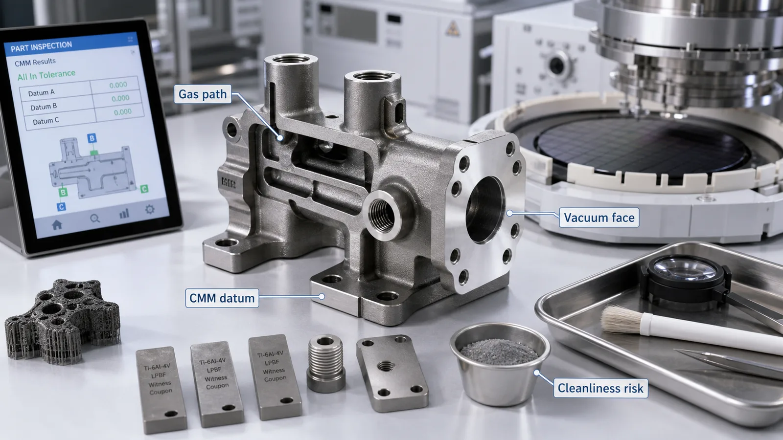
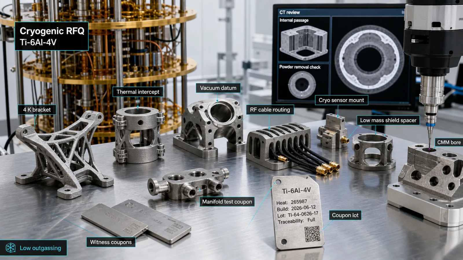
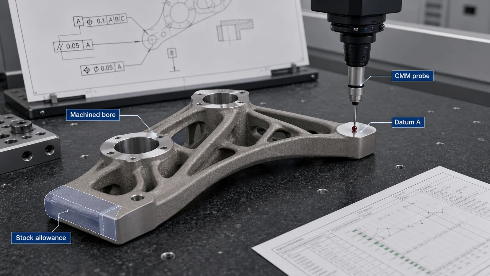
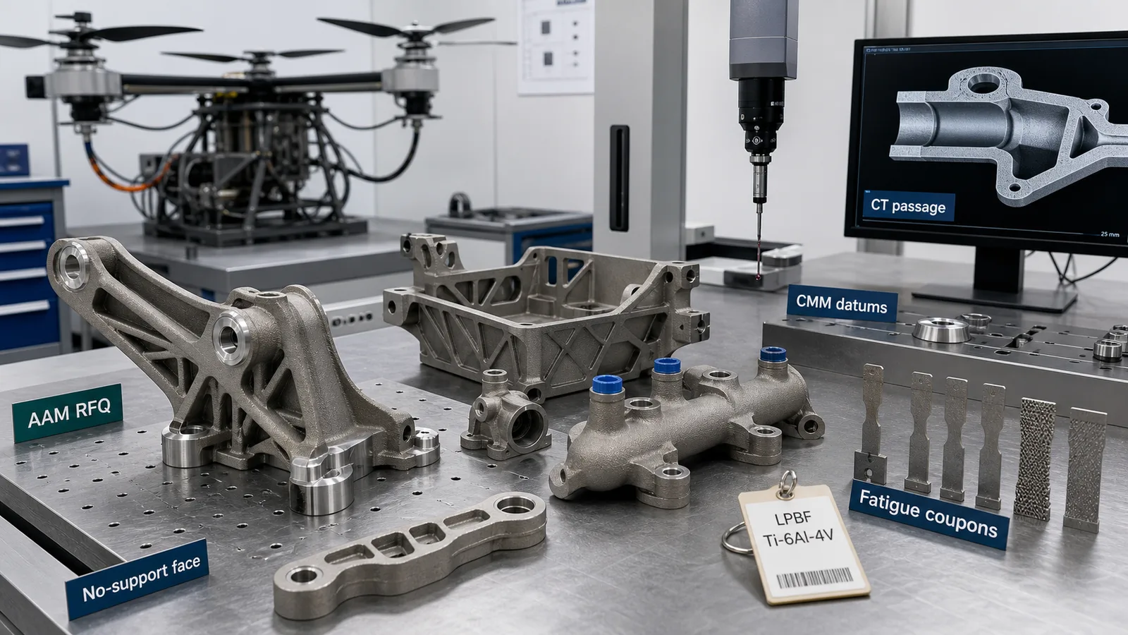
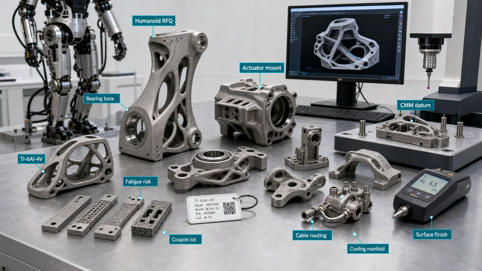
Representative article image; not a customer acceptance record or proof of a qualified manufacturing route. Refer to the cited sources and part-specific inspection records for engineering evidence.
On this page
Titanium 3D printing for semiconductor equipment parts is valuable when a component needs compact routing, corrosion resistance, low-volume iteration, stiffness, thermal stability, or assembly reduction that conventional machining cannot deliver efficiently. It is not valuable simply because the part is used near a fab tool.
Semiconductor equipment hardware is unforgiving. A printed titanium gas manifold, vacuum adapter, wafer handling bracket, sensor mount, cooling body, or process fixture must control particles, trapped powder, sealing surfaces, datum geometry, cleaning route, and documentation. If those details are left out of the RFQ, the quote may price a printed shape instead of a part that can be accepted into an equipment build.
For a broad application map, start with Titanium 3D Printing Applications and use this guide for semiconductor-equipment-specific RFQ decisions. For quantum computing, dilution refrigerator, and cryogenic vacuum support hardware, use Titanium 3D Printing for Quantum Computing and Cryogenic Hardware instead.
Quick Answer
Titanium additive manufacturing is worth reviewing for semiconductor equipment when the part is compact, high-value, geometry-constrained, corrosion-exposed, vacuum-adjacent, or tied to fast engineering iteration.
Candidate families for feasibility review, not a list of qualified semiconductor parts, include:
- Titanium gas manifolds with complex internal routing and fewer external fittings.
- Vacuum-interface adapters where machined sealing faces, datum control, cleaning, and vacuum verification are planned.
- Wafer handling brackets, sensor mounts, and robot-adjacent hardware where stiffness and mass matter.
- Process tooling, shields, brackets, and fixtures exposed to heat, corrosion, or repeated maintenance.
- Thermal management blocks or cold plates that combine cooling channels with mounting structure.
- Low-volume engineering spares where tooling delay or supplier lead time is the main risk.
- Test, metrology, and pilot-line hardware where revision speed matters more than high-volume unit cost.
Weak candidates include simple plates, commodity aluminum brackets, large low-stress covers, high-volume machined blocks, cosmetic covers, and any particle-sensitive part where powder removal, surface finish, cleaning, and acceptance evidence are not funded.
If the part can be machined, fabricated, or assembled conventionally with lower cleanliness and acceptance risk, use the When Not to Use Titanium Additive Manufacturing screen before requesting production pricing.
Separate Structural Hardware From Process-Contact Parts
Classify each surface before asking for a production quote. A bracket outside the tool does not have the same acceptance basis as a process-gas manifold or a wafer-adjacent moving part.
| Exposure class | Requirements to define | Hold point before production |
|---|---|---|
| External, non-process support | Load, datum stability, environment, and maintenance access | Confirm material and finished-interface suitability |
| Wafer-adjacent or moving hardware | Particle generation, rubbing/contact surfaces, cleaning, handling, and packaging | Agree measurable contamination criteria with the equipment owner |
| Inside vacuum or part of its boundary | Surface state, cleaning/bake history, gas load, seal design, and leak criterion | Demonstrate the relevant outgassing and leak performance of the proposed route |
| Process-gas or chemical contact | Exact species, temperature, pressure, internal finish, and residue limits | Confirm material compatibility and a validated cleaning/verification route |
If the process owner cannot define these requirements, limit the RFQ to feasibility or controlled development work. Neither a dense print nor a cleanroom label establishes acceptance for all four classes.
Industry spending reports such as SEMI’s equipment outlook describe market context only; they are not evidence of cleanliness, vacuum performance, or this supplier’s qualification.
Where Titanium AM Fits in Semiconductor Equipment
Titanium is not a default replacement for stainless steel, aluminum, ceramics, polymers, or nickel alloys. It earns a review when its corrosion resistance, strength-to-weight ratio, low-volume manufacturability, thermal behavior, or geometry freedom creates a delivered system benefit.
| Part family | Why titanium AM can help | Main RFQ risk | Evidence to define |
|---|---|---|---|
| Gas manifold or routing block | Curved internal paths, fewer fittings, compact footprint | Powder removal and cleanliness | CT or flow check, cleaning route, residual powder rule |
| Vacuum adapter or chamber interface | Integrated ports and compact geometry | Sealing face quality | Machining stock, leak test, CMM datum report |
| Wafer handling or robot bracket | Lower mass and high stiffness near motion axes | Datum repeatability and particles | Machined interfaces, surface finish, cleaning evidence |
| Sensor or metrology mount | Stiff position in a constrained envelope | Vibration and CMM control | Datum plan, flatness, bore position |
| Thermal management block | Channels plus mounting structure | Internal roughness and pressure testing | Flow test, CT if hidden paths matter, leak test |
| Process fixture or shield | Low-volume, corrosion-resistant custom hardware | Surface condition and maintenance exposure | Alloy, finish, cleaning, replacement records |
The right application is one where additive geometry simplifies the tool or shortens the engineering path. The wrong application is one where titanium AM adds cleaning, inspection, and documentation burden without improving the equipment outcome.
For thermal hardware, see Titanium 3D Printed Heat Exchangers. For robot-adjacent wafer handling or automation brackets, see Titanium 3D Printing for Robotics and Automation Parts.
Cleanliness Is the First Design Constraint
A semiconductor equipment RFQ should treat cleanliness as a design input, not a final wash step. Titanium powder-bed parts can contain rough surfaces, support scars, trapped powder, partially sintered particles, and internal cavities that are difficult to inspect or clean. Those risks matter more near wafers, gas paths, vacuum interfaces, or maintenance regions.
Before quotation, define:
- Whether the part is in a process area, utility area, test fixture, or noncritical support location.
- Whether the part is exposed to vacuum, process gases, purge gas, coolant, chemicals, or only ambient air.
- Whether particles, trapped powder, or rough internal surfaces are rejectable.
- Which surfaces require machining, polishing, passivation, cleaning, coating, or special packaging.
- Whether cleaning evidence, inspection photos, CT, flow test, leak test, or particle review is required.
- Whether the part is prototype, engineering test, tool build, field spare, or production hardware.
Do not assume that a printed titanium part is cleanroom-ready because it is metal. Acceptance depends on the route, not the label.
Internal Gas Paths and Powder Removal
Gas manifolds and compact routing bodies are among the most attractive semiconductor equipment candidates because additive manufacturing can reduce plugs, cross-drilled holes, fittings, dead legs, and assembly joints. The same geometry can fail if powder removal and inspection are weak.
High-risk features include:
- Blind internal channels.
- Long tortuous gas paths with no cleaning access.
- Small restrictions that partially sintered powder can block.
- Internal ledges where particles collect.
- Ports that require sealing but lack machining stock.
- Multiple circuits separated by thin walls without leak or CT assumptions.
- Internal lattice or weight-reduction voids connected to functional gas paths.
The article on Titanium 3D Printed Internal Channels covers powder removal and CT in detail. For semiconductor equipment, the same issue has a stricter consequence: residual powder is not only a blockage risk, it can be a cleanliness and contamination risk.
Vacuum Faces, Seals, and Leak Testing
Any vacuum-adjacent titanium AM part needs a clear plan for sealing faces, bolt patterns, flatness, surface condition, and leak testing. The printed shape should not be expected to provide the final sealing surface.
NIST’s comparison of seven vacuum chambers measured water and hydrogen outgassing for defined materials and treatment histories. It is a useful example of specifying a measurement basis, not proof that an LPBF titanium manifold will reproduce those results. The publication does not establish a semiconductor acceptance limit for your component.
Keep leak testing and outgassing assessment separate in the RFQ. Ask for the test configuration, preparation and bake history where applicable, measurement method, time/temperature conditions, background treatment, and acceptance criterion. Specify particle or residue checks independently; passing one test does not establish the others. Use the qualification and inspection guide to define which records belong in the delivered scope.
Define:
- Which faces are vacuum or gas sealing surfaces.
- Gasket, O-ring, metal seal, or custom interface assumptions.
- Machining stock on seal faces, counterbores, threads, and ports.
- Flatness, surface roughness, and bore position requirements.
- Working pressure, vacuum level, leak rate, or pressure-hold basis.
- Whether testing happens before or after final cleaning and packaging.
- Whether helium leak testing, pressure testing, or a simpler development check is required.
Weak wording:
Include leak testing.
Better wording:
Include final machining of the vacuum sealing face and a leak test after cleaning. Please define the proposed test method, fixture assumption, leak threshold, port sealing method, and whether CT before testing is recommended for the internal gas path.
That wording helps procurement compare delivered acceptance, not only printing cost.
Datum Planning for Equipment Integration
Semiconductor equipment components often assemble into precise tool stacks. A gas manifold may need ports aligned to tubing. A wafer handling bracket may need stable end-effector geometry. A metrology mount may need a fixed optical or sensor relationship. A vacuum adapter may need bolt holes and seal faces measured to datums.
Define:
- Primary datum face and secondary locating features.
- Machined seal faces, bolt circles, threads, ports, and sensor planes.
- Surfaces allowed to remain as-built.
- CMM report scope and pass/fail dimensions.
- Any calibration, alignment, or tool-teaching surfaces.
- Whether the part is interchangeable across tools or tied to one prototype build.
Do not ask a supplier to infer precision from the model. The drawing should identify what must be machined and measured. Use Titanium 3D Printing Tolerances: Datum Planning and CMM before locking the RFQ.
Material Selection: Titanium Grade and Exposure
Ti-6Al-4V is often the first titanium AM review route because it is familiar to many suppliers and performs well in high-strength compact parts. Ti-6Al-4V ELI may be reviewed when ductility, fracture behavior, or a tighter acceptance basis is required. CP titanium may be more relevant when corrosion resistance, chemical compatibility, ductility, or purity-related constraints matter more than high strength.
The material decision should follow the actual equipment environment:
- Process gas, purge gas, coolant, solvent, or chemical exposure.
- Vacuum, temperature, and thermal cycling.
- Wear, sliding contact, or maintenance handling.
- Strength, stiffness, and bolt preload.
- Cleaning, passivation, coating, or surface treatment route.
- Documentation level and supplier material traceability.
Do not specify a titanium alloy only because it is available for LPBF. Tie the alloy to exposure, strength, and acceptance. For alloy comparison, use Titanium AM Material Selection: Ti-6Al-4V, ELI, and CP Titanium.
Process Choice: LPBF Is Common, but Not Automatic
LPBF is usually the first process reviewed for compact semiconductor equipment parts because it supports fine geometry, internal routing, brackets, manifolds, and high-value low-volume hardware. EBM may be considered when the supplier route, surface expectations, and geometry fit. DED is usually a better conversation for larger near-net shapes, repair, or machining-stock parts rather than fine clean internal paths.
Process choice changes:
- Minimum channel size and powder-removal feasibility.
- As-built surface texture and particle risk.
- Support contact location.
- Distortion on sealing faces.
- Stress relief, HIP, machining, and finishing sequence.
- CT, CMM, leak test, and cleaning scope.
- Cost and lead time.
Use Titanium AM Process Selection: LPBF vs EBM vs DED when the supplier should recommend the route instead of only quoting a process named in the drawing.
DfAM Rules for Semiconductor Equipment Parts
DfAM for semiconductor hardware should reduce acceptance risk, not only make the part look optimized.
Useful rules include:
- Keep supports away from seal faces, datum faces, ports, and cleaned internal openings.
- Add machining stock to sealing faces, ports, threads, bolt pads, and datum surfaces.
- Avoid blind cavities and internal features that cannot be cleaned or inspected.
- Separate functional gas paths from weight-reduction voids.
- Keep particle-sensitive surfaces accessible for finishing and cleaning.
- Use smooth transitions in internal channels to reduce powder traps.
- Avoid unnecessary lattice structures near process or vacuum regions.
- Define which surfaces can remain as-built and which require finishing.
- Add witness coupons when the acceptance basis requires material or process evidence.
The broader support, overhang, trapped-powder, and thin-wall rules are covered in Titanium DfAM Rules for LPBF and EBM.
Surface Finish, Post-Processing, and Cleaning
Surface condition is one of the largest differences between an attractive printed CAD model and an acceptable semiconductor equipment part. Some exterior surfaces may remain as-built. Seal faces, ports, threads, contact faces, and particle-sensitive regions usually need machining or finishing.
Common post-processing considerations include:
- Stress relief and heat treatment.
- HIP if justified by pressure boundary, fatigue, or density requirements.
- Support removal and local blending.
- Machining of seal faces, ports, threads, bolt patterns, datums, and contact features.
- Surface finishing, passivation, coating, or polishing where the application requires it.
- Cleaning, drying, packaging, and handling controls.
- Inspection after final cleaning, not only after printing.
Use Post-Processing for Titanium 3D Printing when defining the delivered condition. A quote that omits finishing and cleaning may be cheap because it is incomplete.
Inspection Evidence: Match the Risk
Semiconductor equipment parts can be over-tested or under-tested. The right evidence depends on whether the part is a noncritical bracket, a vacuum interface, a gas path, a thermal block, or a production tool component.
Typical evidence includes:
- CMM report for datums, ports, seal faces, bolt patterns, and critical interfaces.
- CT inspection for internal gas paths, hidden powder traps, wall thickness, or blockages when risk justifies it.
- Leak or pressure test for vacuum or gas-carrying parts.
- Flow test where channel openness affects function.
- Surface roughness checks on seal, contact, fatigue, or cleaned regions.
- Material certification, COA, COC, heat-treatment record, build record, powder lot, and traceability.
- Cleaning record, packaging note, and inspection photos where cleanliness risk is relevant.
Use Titanium AM Qualification and Inspection Evidence to select evidence by risk class. Requesting every test for every prototype can waste budget. Requesting no evidence for a hidden gas path can make the part unacceptable.
Cost: Compare Accepted Equipment Hardware
Titanium AM can reduce assembly count, shorten low-volume lead time, and create compact routing. It can also hide cost in post-processing and acceptance.
Cost drivers include:
- Build orientation and support strategy.
- Support removal from ports, ribs, and internal openings.
- Stress relief, HIP if needed, and heat treatment.
- Machining of seal faces, threaded ports, bolt circles, datums, and contact faces.
- CT, CMM, leak testing, flow testing, roughness checks, and documentation.
- Cleaning, drying, packaging, and handling requirements.
- Rework if powder remains in a hidden path.
- Revision iteration during tool integration.
Control cost by separating functional surfaces from noncritical surfaces, allowing supplier DfAM feedback before the drawing is frozen, and defining the evidence needed for this risk class. For quote normalization, use Titanium 3D Printing Cost Drivers: How to Reduce RFQ Price and the Titanium AM RFQ and Procurement Guide.
Better RFQ Wording
Weak RFQ:
Please quote this titanium 3D printed semiconductor manifold.
Better RFQ:
Please review this Ti-6Al-4V or CP titanium component for LPBF production. The internal gas path is functional and must be cleanable. Critical features are the machined vacuum face, threaded ports, bolt pattern, and three CMM datums. Please identify powder-removal access, support strategy, machining stock, final cleaning route, CT or flow-test feasibility, leak-test assumptions, CMM scope, material traceability, and any DfAM changes needed before quotation. Quote the delivered accepted part, not only the printed shape.
That wording helps the supplier price the route that matters: print, stress relieve, depowder, finish, machine, clean, inspect, test, document, and package.
RFQ Checklist
Send the supplier:
- STEP file and drawing with datums, section views, and critical surfaces.
- Target alloy, material condition, and whether substitutions are allowed.
- Quantity, prototype or production intent, and target lead time.
- Equipment context: vacuum, process gas, purge gas, coolant, chemical, heat, or ambient support use.
- Cleanliness and particle assumptions, including whether residual powder is rejectable.
- Functional interfaces: seal faces, O-ring grooves, ports, threads, bolt holes, sensor datums, wafer handling interfaces, and contact pads.
- Internal channel information: minimum feature size, blind regions, powder-removal access, and accepted internal roughness.
- Post-processing: stress relief, HIP if justified, machining, finishing, passivation, cleaning, packaging, and labeling.
- Inspection: CMM, CT, leak test, pressure test, flow test, roughness, coupons, COA, COC, build record, powder lot, and inspection report.
- Permission for supplier DfAM changes before final pricing.
If the RFQ does not define cleaning, sealing, datum, and evidence assumptions, suppliers may quote very different products under the same part number.
When to Redesign or Avoid Titanium AM
Redesign before quotation when:
- A functional gas path has no powder exit.
- Vacuum or seal faces lack machining stock.
- Internal channels cannot be cleaned or inspected.
- Particle-sensitive surfaces are rough, supported, or unreachable.
- CT cannot resolve the smallest critical feature.
- Leak testing is required but the test method and threshold are undefined.
- A simple machined part would meet the requirement with lower risk.
Avoid titanium AM when conventional machining, fabrication, casting, or assembled tubing delivers the same function with lower cost, cleaner surfaces, shorter acceptance time, or better supplier availability.
Bottom Line
Titanium 3D printing is a candidate route when geometry or low-volume iteration creates a benefit that can be verified. Screen external supports separately from wafer-adjacent, vacuum, and process-contact parts. Gas manifolds and vacuum interfaces should remain conditional candidates until material compatibility, cleaning, outgassing or leak requirements, and the supplier’s verification route are resolved.
The weak cases are simple shapes and any particle-sensitive part where the RFQ ignores powder removal, surface finish, cleanliness, sealing, and acceptance evidence.
For an RFQ review, send CAD, drawing, equipment context, process exposure, cleanliness requirement, target alloy, quantity, post-processing expectations, and inspection scope through the RFQ inputs page or email info@szcomo.com.
- Semiconductor
- Vacuum
- Gas manifolds
- Cleanliness
- Wafer handling
- LPBF
- CMM
- RFQ