· Updated - TITANIUM 3DP Engineering - Engineering Guides - 13 min read
Titanium 3D Printing for Robotics and Automation Parts
Engineering RFQ guide for titanium 3D printed robotics parts, including EOAT, grippers, lightweight wrist adapters, automation fixtures, fatigue, CMM, and cost control.
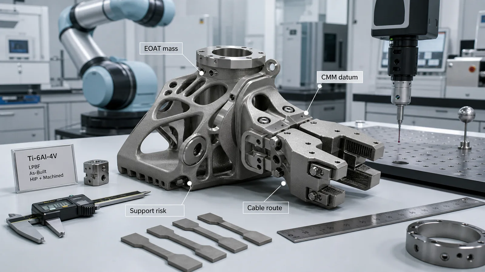
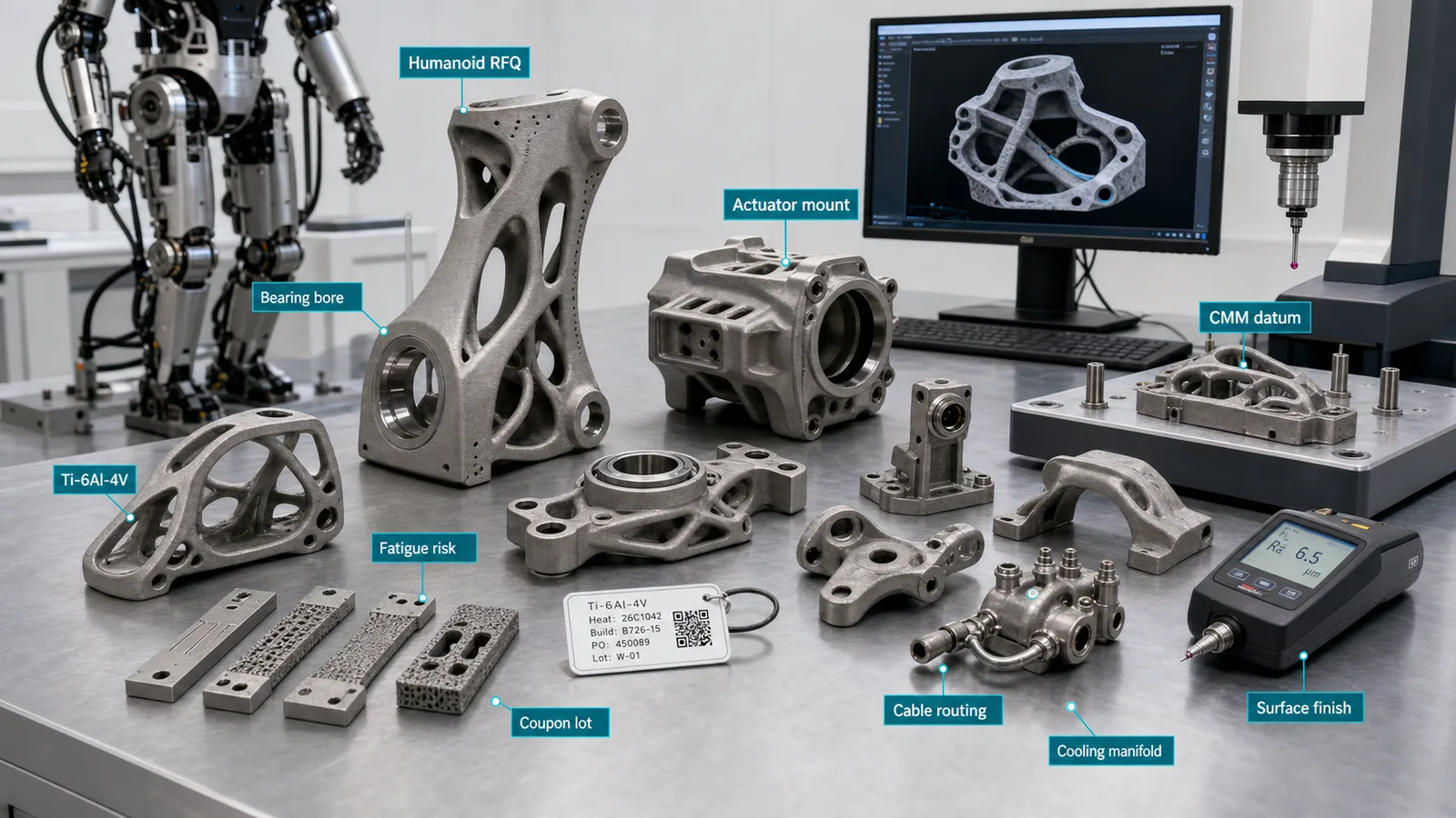
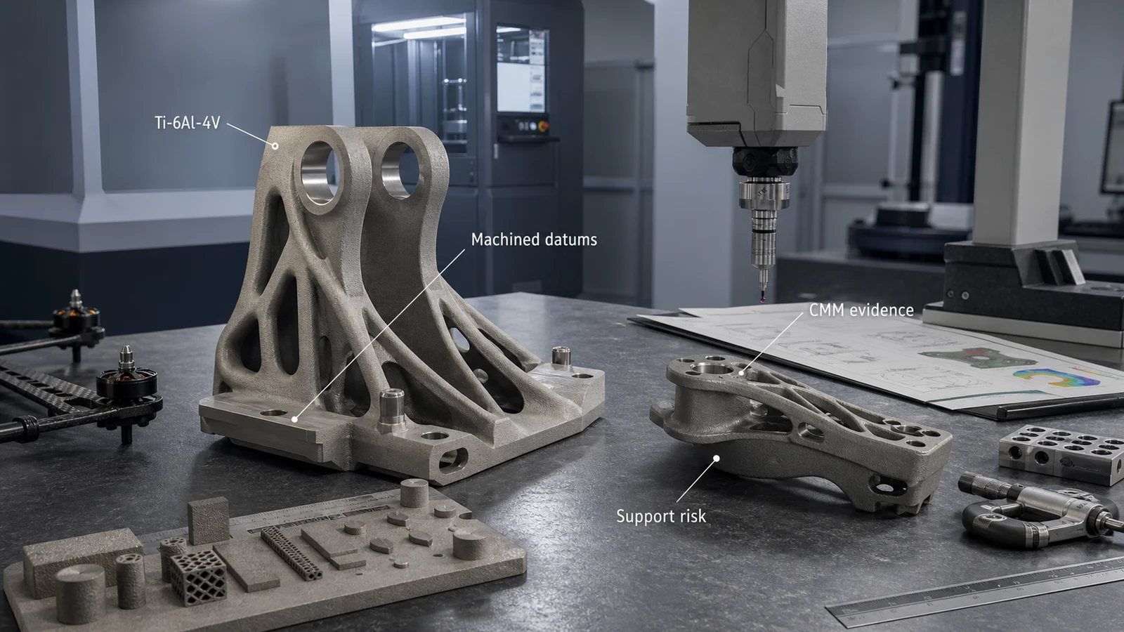
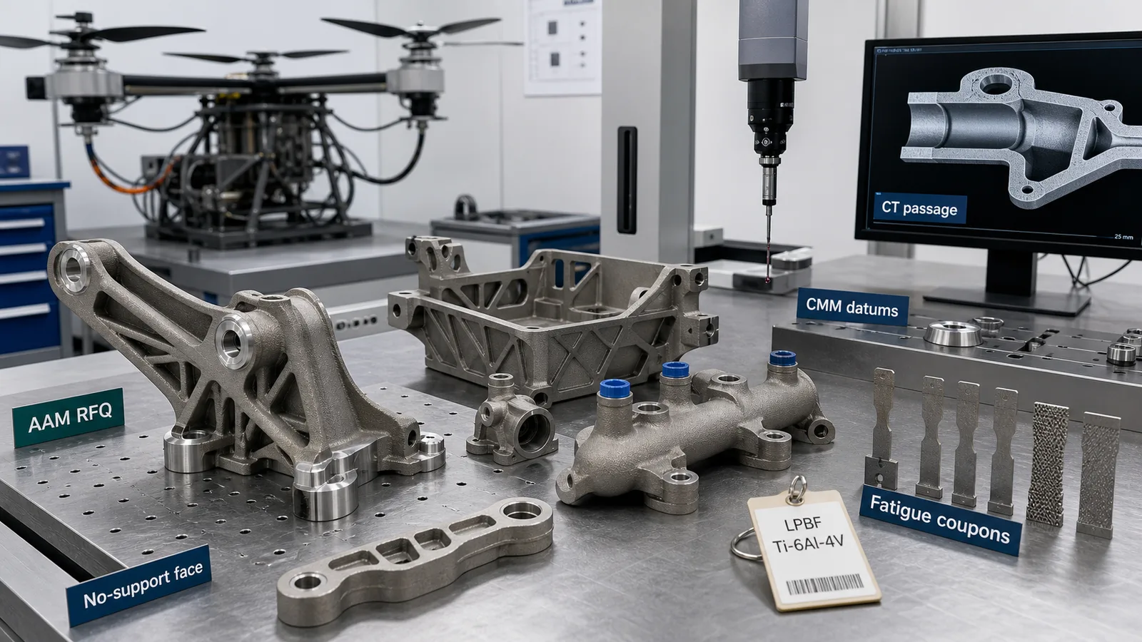
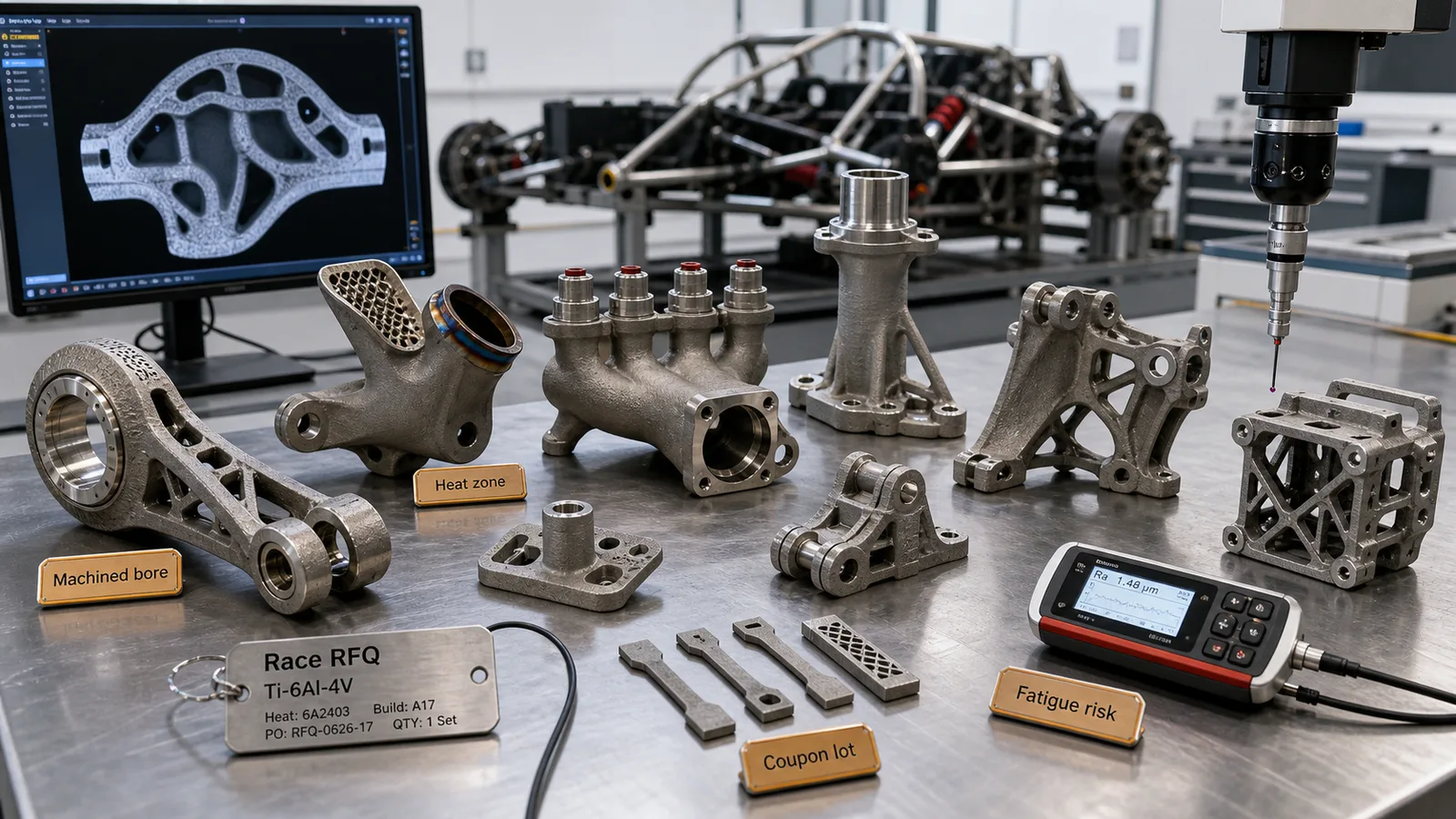
Representative article image; not a customer acceptance record or proof of a qualified manufacturing route. Refer to the cited sources and part-specific inspection records for engineering evidence.
On this page
Titanium 3D printing for robotics and automation parts is valuable when a robot tool, wrist adapter, gripper, fixture, or compact handling component needs lower mass, higher stiffness, better packaging, corrosion resistance, or faster low-volume iteration. It is not valuable merely because the part belongs to a robot.
In automation, every gram at the wrist can affect payload margin, acceleration, cycle time, vibration, brake wear, motor load, and the size of the robot selected for the cell. A titanium additive manufacturing route can help when it removes unnecessary mass while preserving stiffness and datum control. It can also make the quote more expensive if support removal, machining, CMM, fatigue, and safety evidence are not defined before procurement compares suppliers.
For a broader application map, start with Titanium 3D Printing Applications and use this guide for robotics-specific RFQ decisions.
For humanoid robots and embodied-AI hardware, use Titanium 3D Printing for Humanoid Robots and AI Robotics Hardware to review joints, actuator housings, wrist and ankle brackets, fatigue, bearing bores, and RFQ evidence.
Quick Answer
Titanium additive manufacturing is worth reviewing for robotics and automation parts when the component is compact, high-value, interface-heavy, motion-sensitive, or exposed to repeated loads, washdown, heat, corrosion, or space constraints.
Good candidates include:
- End-of-arm tooling brackets where lower mass improves robot payload or acceleration margin.
- Lightweight gripper fingers, jaws, and wrist adapters with machined datum faces.
- Robot-mounted camera, laser, sensor, or inspection brackets where stiffness protects measurement repeatability.
- Compact pneumatic, vacuum, coolant, or cable-routing bodies with internal passages.
- Automation fixtures, nest plates, and changeover hardware that need high stiffness in a small envelope.
- Corrosion-resistant handling parts for wet, chemical, marine, or process environments.
- Low-volume production tooling where design iteration is faster than machining multiple billet versions.
- Replacement or retrofit hardware where the original supply chain is slow or obsolete.
Weak candidates include simple plates, large low-stress covers, commodity aluminum brackets, high-volume stamped tooling, cosmetic robot shells, and any EOAT part where titanium does not improve payload, stiffness, durability, corrosion resistance, or lead time.
If the decision is still broad, run the When Not to Use Titanium Additive Manufacturing screen before asking for production pricing.
Why Robotics Hardware Is Timely in 2026
Robotics is receiving more attention in 2026 because AI, labor pressure, reshoring, industrial productivity, and humanoid robot demonstrations have pushed automation into board-level conversations. That attention does not make every robot part a titanium AM candidate, but it does explain why more engineers are reviewing lightweight, documented, fast-iteration hardware for robot cells.
Recent public signals are useful context:
- The International Federation of Robotics reported in May 2026 that China placed robotics at the center of its next industrial strategy and noted that industrial robots remain the backbone of high-speed, precision-driven manufacturing environments.
- The Association for Advancing Automation reported that North American companies ordered 9,055 robots worth $543 million in Q1 2026, while non-automotive sectors such as life sciences, electronics, food, and general industry posted strong gains.
- ISO 10218-1:2025 and ISO 10218-2:2025 keep industrial robot safety, integration, applications, and cells in a current standards conversation.
The practical takeaway for a titanium RFQ is simple: robot hardware is not only a geometry problem. It is part of a moving system with payload, speed, safety, risk reduction, maintenance, and repeatability requirements.
Where Titanium AM Fits in Robot Cells
Titanium is not the default material for automation. Aluminum, steel, carbon fiber, polymers, and conventional machining often win. Titanium earns a review when the part is small enough, valuable enough, and difficult enough that the delivered route creates a measurable cell benefit.
| Part family | Why titanium AM can help | Main hidden cost | Evidence to define |
|---|---|---|---|
| EOAT bracket or wrist adapter | Lower wrist mass with high stiffness and compact load paths | Machined datum faces and CMM setup | Datum plan, bolt pattern, flatness, CMM report |
| Gripper fingers or jaws | Custom geometry, local stiffness, wear-resistant interfaces | Machining of contact and fastener surfaces | Contact faces, thread inserts, surface finish |
| Robot-mounted sensor bracket | Stiff sensor position with cable routing and low inertia | Vibration and datum control | CMM, surface finish, modal or proof check if needed |
| Vacuum or pneumatic manifold | Fewer tubes, fittings, and leak paths | Powder removal and leak testing | CT if hidden paths matter, pressure or leak test |
| Changeover fixture | Lightweight high-stiffness tooling for faster setup | Post-processing and repeatability | CMM, revision control, traceability |
| Corrosion-resistant handling tool | Titanium compatibility in wet or chemical environments | Material and cleaning route | Alloy, passivation, cleaning, surface condition |
The part becomes a good additive candidate when mass reduction, stiffness, routing, and assembly reduction improve the robot cell. It is not enough for the CAD model to look organic.
For general lightweighting logic, see Titanium Additive Manufacturing Applications That Achieved Real Weight Reduction.
EOAT Mass Changes the Robot Decision
End-of-arm tooling is a strong robotics use case because the tool sits far from the robot base. Mass at the wrist can reduce available payload, lower allowable acceleration, increase stopping distance, and push the buyer toward a larger robot. A bigger robot can mean more floor space, higher energy use, higher capital cost, and more demanding guarding or integration.
Titanium AM can help when it reduces EOAT mass without sacrificing stiffness, interface flatness, or durability. The design should focus on the cell outcome:
- Lower tool mass at the same stiffness.
- Better acceleration or cycle-time margin.
- Reduced vibration at the gripper, camera, or process tool.
- Fewer adapter plates and fasteners.
- Integrated cable, air, vacuum, or coolant routing.
- A smaller robot selection because the payload margin is now acceptable.
The RFQ should not ask for the lightest possible bracket. It should define the robot model, payload margin, center-of-gravity limit, acceleration profile, tool offset, and the surfaces that must remain stiff and measurable.
Stiffness and Vibration Matter More Than Shape
Robot hardware often fails the business case when the printed part is light but too compliant. A gripper can be lighter and still miss repeatability if the fingers flex. A camera bracket can be attractive in CAD and still blur inspection data if it moves under acceleration. A wrist adapter can survive static load and still create vibration problems at the cell’s operating speed.
High-risk features include:
- Thin ribs tied directly into thick bosses.
- Sharp topology transitions near bolt patterns.
- Support scars on loaded tensile surfaces.
- As-built holes used as precision fastener locations.
- Long cantilevered sensor mounts.
- Lattice transitions near clamp or bearing regions.
- Cable passages that cut through the main load path.
Use Titanium 3D Printing Fatigue Design when the part sees repeated acceleration, gripping cycles, impact, or vibration. Static strength is only one part of a robotics review.
Datum Planning for Robot Repeatability
Automation parts often depend on repeatable position. The printed shape is not the final accepted shape if the part needs a tool-center-point interface, camera position, gripper jaw alignment, or precision bolt pattern.
Define datums early:
- Robot flange face and bolt circle.
- Tool-center-point related surfaces.
- Gripper jaw or finger contact faces.
- Sensor mounting planes and bores.
- Quick-change coupler faces.
- Fixture locating pins, nests, and clamp pads.
- Machined faces for calibration or re-teaching.
The drawing should separate surfaces that can remain as-built from surfaces that need machining. Add stock to the faces that need flatness, bore position, thread quality, or repeatable contact. For detailed wording, use Titanium 3D Printing Tolerances: Datum Planning and CMM.
Material Selection: Ti-6Al-4V Is Common, but Not Automatic
Ti-6Al-4V is usually the first alloy reviewed for high-stiffness titanium robotics hardware because it has strong AM supplier familiarity and high strength-to-weight performance. Ti-6Al-4V ELI may be relevant when ductility, fracture behavior, or a tighter acceptance basis matters. CP titanium may be relevant for corrosion resistance or chemical compatibility when high strength is not the main driver.
The material line should follow the application:
- Load, shock, and gripping force.
- Cycle count and vibration exposure.
- Contact wear or jaw surface condition.
- Corrosion, washdown, chemical, or temperature exposure.
- Whether the part is prototype, production tooling, or safety-related cell hardware.
- Required documentation level and traceability.
Do not specify ELI, CP titanium, or HIP only because the part is important. Specify them when they answer a risk. For alloy selection, see Titanium AM Material Selection: Ti-6Al-4V, ELI, and CP Titanium.
Process Choice: LPBF Usually Leads for EOAT and Grippers
LPBF is often the first route for compact robotics parts because it supports fine features, weight-saving ribs, internal channels, cable passages, and small structural nodes. EBM may be considered when the supplier route fits the geometry and surface expectations. DED is usually a different conversation, more relevant to larger near-net tooling, repair, or machining-stock features than small gripper hardware.
Process choice affects:
- Minimum feature size and wall thickness.
- Support contact and no-support surface planning.
- Distortion in flat datum regions.
- Internal passage cleaning.
- Surface finish at fatigue or clamp areas.
- Machining stock and fixture setup.
- CMM, CT, coupons, and traceability scope.
Use Titanium AM Process Selection: LPBF vs EBM vs DED if the supplier should recommend the route instead of only quoting a print process named in the RFQ.
DfAM Rules for Robotics Parts
Robotics DfAM is not only about removing material. It is about controlling motion, interfaces, and post-processing.
Useful rules include:
- Keep supports away from fatigue-critical, clamp, datum, and contact surfaces.
- Add machining stock on robot flange faces, bolt bores, jaw interfaces, and sensor datums.
- Use smooth rib transitions around load paths.
- Avoid hidden lattices where cleaning and inspection are weak.
- Keep cable and air passages out of critical tensile paths.
- Design jaws and grippers so wear surfaces can be replaced, machined, coated, or inserted.
- Separate cosmetic weight-saving cavities from functional load paths.
- Make tool-change features accessible for inspection and maintenance.
- Define all no-support surfaces before the supplier chooses build orientation.
The broader support, thin-wall, overhang, and trapped-powder rules are covered in Titanium DfAM Rules for LPBF and EBM. If a part includes internal air, vacuum, coolant, or cable passages, also use Titanium 3D Printed Internal Channels.
Internal Routing: Helpful, but Easy to Underquote
Robot tools often carry cables, air lines, vacuum, coolant, sensor wiring, or process gas. Additive manufacturing can integrate those paths, but internal routing adds acceptance risk.
Define:
- Whether the passage is only cable clearance or a pressure path.
- Powder-removal access.
- Minimum internal feature size.
- Whether blockage, roughness, or residual powder is rejectable.
- Whether CT, borescope, leak, pressure, or flow testing is required.
- Whether the passage exits near machined sealing faces or fittings.
Internal passages should simplify the cell, not hide cost. A tube clipped outside a bracket may be cheaper and more maintainable than an internal passage that cannot be cleaned or inspected.
For valve blocks, pneumatic manifolds, actuator manifolds, and pressure-tested robot fluid-power hardware, use Titanium 3D Printing for Hydraulic Manifolds and Fluid Power Components to define ports, cleaning, leak testing, CT, and CMM evidence.
Safety and Integration Evidence
Robot standards do not turn a titanium AM bracket into a certified robot system, but they are a reminder that tooling is part of a safety and integration context. ISO 10218-1 focuses on industrial robots themselves, while ISO 10218-2 addresses robot applications and cells. The exact safety responsibility depends on the manufacturer, integrator, user, and application.
For a titanium AM component, the practical RFQ evidence may include:
- Design load and safety factor basis.
- Proof load or functional cycle test if risk justifies it.
- CMM report for datum and interface features.
- Surface finish on fatigue or clamp regions.
- Material certificate, heat-treatment record, build record, and powder lot.
- Inspection report for support removal, machined features, and critical surfaces.
- CT or leak testing only when hidden geometry or pressure paths require it.
- Revision control so replacement tools match the accepted geometry.
Use Titanium AM Qualification and Inspection Evidence to decide which evidence belongs in the quote. Do not request every possible test for a simple prototype, but do request the evidence that answers the actual cell risk.
Cost: Compare Delivered Tooling, Not Printed Shapes
Titanium robotics parts can be attractive when they reduce robot size, cycle time, assembly count, or replacement delays. They can also become expensive if procurement compares a print-only quote against a delivered tool with machining, inspection, and documentation.
Cost drivers include:
- Build orientation and support volume.
- Support removal from ribs, jaws, and adapter pockets.
- Stress relief, HIP if justified, and heat treatment.
- Machining of flange faces, bores, threads, jaw contacts, and sensor datums.
- CMM setup and fixture time.
- Surface finishing at fatigue, clamp, or contact areas.
- Cleaning of internal routing.
- Revision iteration for robot reach, payload, and collision clearance.
- Documentation level required by the integrator or end user.
Control cost by specifying which surfaces are functional, allowing noncritical surfaces to remain as-built, protecting supports from critical regions, and allowing supplier DfAM feedback before the drawing is frozen. For quote normalization, use Titanium 3D Printing Cost Drivers: How to Reduce RFQ Price and the Titanium AM RFQ and Procurement Guide.
RFQ Scenario: Lightweight Robot Wrist Adapter
Consider a robot wrist adapter for a machine-tending cell. The current aluminum adapter is simple and cheap, but the complete EOAT assembly is close to the robot payload limit. Cycle time is constrained because acceleration must be reduced to prevent vibration at the gripper. The adapter also carries a small camera bracket and two air lines.
A weak RFQ says:
Please 3D print this robot adapter in titanium.
A better RFQ says:
Please review this Ti-6Al-4V LPBF wrist adapter for a robot EOAT assembly. The goals are lower wrist mass, equal or higher stiffness at the gripper interface, and integrated cable or air clearance without moving the tool-center-point. Critical features are the robot flange face, bolt circle, quick-change face, gripper mounting bores, and camera datum. Please identify support strategy, no-support surfaces, machining stock, stress relief, CMM scope, surface finish at loaded regions, and whether any DfAM changes can reduce mass without reducing stiffness or inspection access. Quote the delivered accepted part, not only the printed shape.
That second RFQ gives the supplier enough information to price the route and enough permission to improve the design.
Robotics Titanium AM RFQ Checklist
Send the supplier:
- STEP file and drawing with datums.
- Robot model, payload limit, tool-center-point location, and center-of-gravity limit.
- Target alloy and material condition.
- Quantity, prototype or production intent, and target lead time.
- Functional interfaces: robot flange, quick-change coupler, gripper jaw faces, sensor datums, bolt holes, threads, and pins.
- Load case: gripping force, acceleration, impact, duty cycle, vibration, and expected cycles.
- Surfaces allowed to remain as-built and surfaces requiring machining or finishing.
- No-support regions and support-removal access limits.
- Internal cable, air, vacuum, or coolant passages with cleaning or leak-test requirements.
- Required post-processing: stress relief, HIP if justified, machining, surface finishing, cleaning, coating, or passivation.
- Inspection and documentation: CMM, roughness, proof load, CT if hidden geometry matters, coupons if needed, COA, COC, build record, powder lot, and inspection report.
- Permission for supplier DfAM changes before final quotation.
If the supplier cannot explain support strategy, machining assumptions, datum control, and inspection scope, the quote is not ready for comparison.
When to Redesign or Avoid Titanium AM
Redesign before quotation when:
- The part is light but too flexible for the robot task.
- Critical bolt patterns or datum faces lack machining stock.
- Supports land on fatigue-critical or clamp regions.
- Cable passages weaken the main load path.
- Internal routing cannot be cleaned or inspected.
- Gripper contact surfaces need wear resistance but no replaceable insert, coating, or machining plan exists.
- Procurement wants a print-only price for a delivered robot tool.
Avoid titanium AM when aluminum, steel, carbon fiber, polymer, or conventional machining already meets payload, stiffness, cycle time, corrosion, and lead-time requirements at lower risk.
Bottom Line
Titanium 3D printing can be valuable for robotics and automation parts when it improves the robot cell: lower EOAT mass, better stiffness-to-weight ratio, cleaner routing, fewer parts, corrosion resistance, or faster low-volume iteration. The strongest candidates are wrist adapters, EOAT brackets, gripper components, sensor mounts, compact manifolds, and changeover tooling where delivered acceptance is clearly defined.
The weak cases are simple plates, commodity brackets, cosmetic robot parts, and any design where titanium does not improve payload, cycle time, repeatability, durability, or sourcing.
For an RFQ review, send CAD, drawing, robot payload context, tool-center-point and center-of-gravity limits, target alloy, quantity, post-processing expectations, and inspection scope through the RFQ inputs page or email info@szcomo.com.
- Robotics
- Automation
- Eoat
- Grippers
- Lightweighting
- DFAM
- Fatigue
- CMM
- RFQ