· Updated - TITANIUM 3DP Engineering - Engineering Guides - 16 min read
Titanium 3D Printing for Quantum Computing and Cryogenic Hardware
Engineering RFQ guide for titanium 3D printed quantum computing and cryogenic hardware, covering dilution refrigerator brackets, vacuum supports, thermal intercepts, RF cable routing, CMM, CT, cleaning, and traceability.
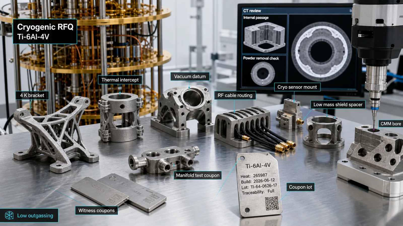
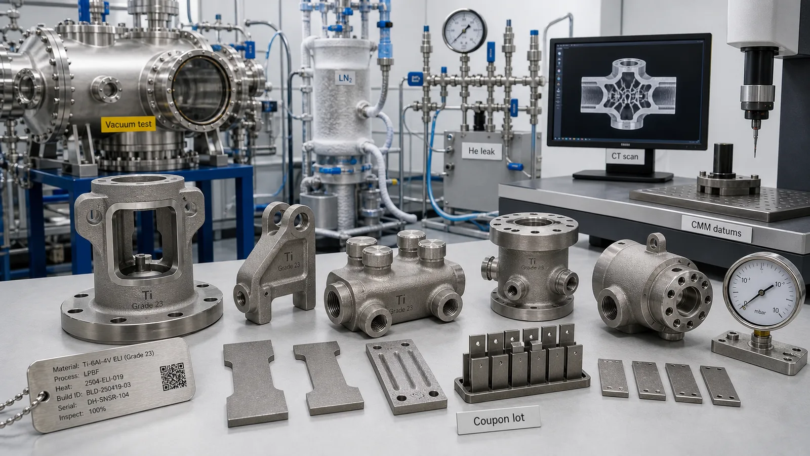
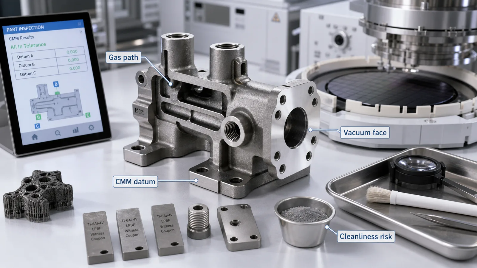
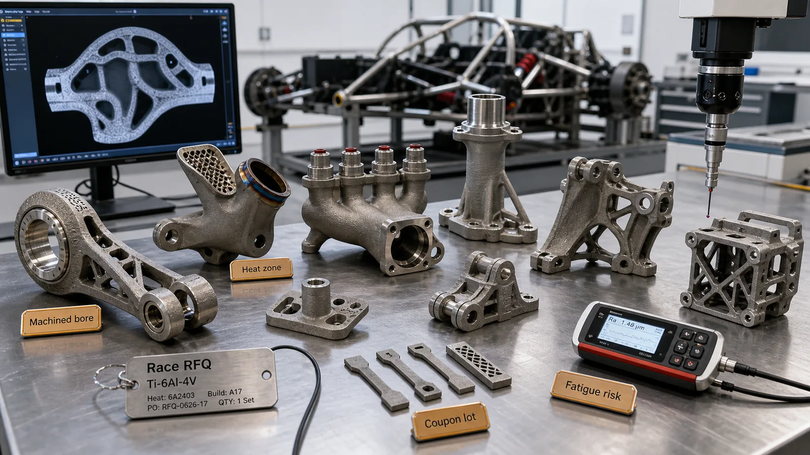
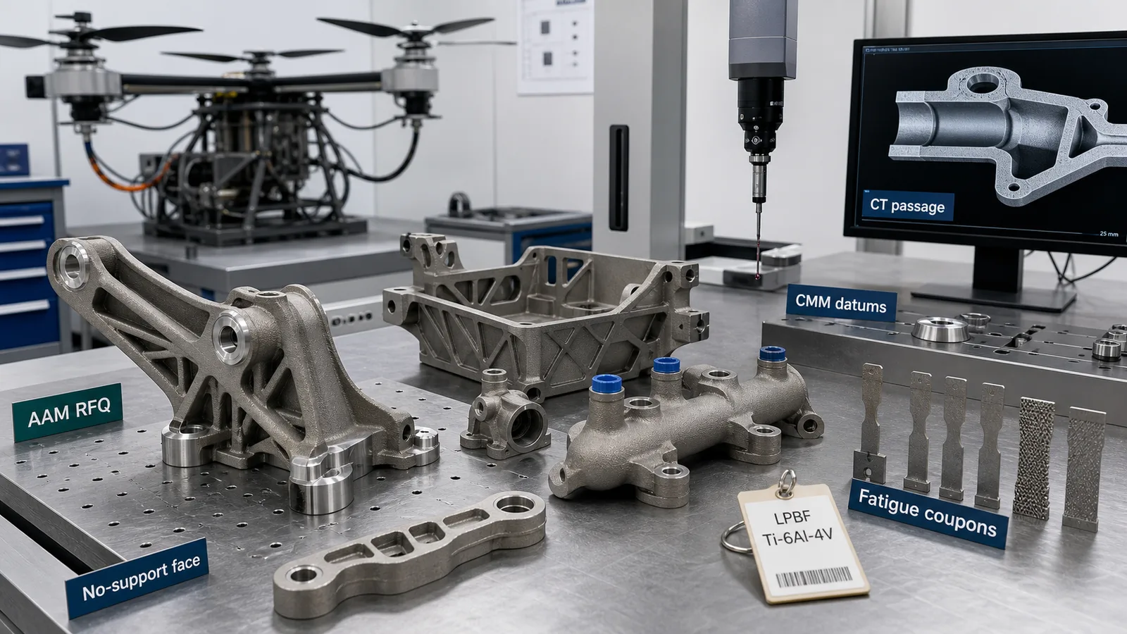
Representative article image; not a customer acceptance record or proof of a qualified manufacturing route. Refer to the cited sources and part-specific inspection records for engineering evidence.
On this page
Titanium 3D printing for quantum computing and cryogenic hardware is worth reviewing when a low-volume part needs low mass, vacuum-compatible geometry, compact cable routing, low heat leak, nonmagnetic behavior, fast laboratory iteration, or documented traceability. It is not a route for printing qubit chips, superconducting devices, high-conductivity copper thermal links, or cleanroom-ready vacuum hardware without a defined acceptance plan.
Quantum hardware is not one application. A superconducting qubit system, trapped-ion system, neutral-atom platform, photonic quantum module, quantum sensor, dilution refrigerator, and low-temperature test fixture all create different mechanical constraints. The practical titanium additive manufacturing question is narrower: where can a printed titanium bracket, shield spacer, thermal-intercept support, vacuum adapter, RF cable clamp, sensor mount, manifold, coupon rack, or test fixture improve the hardware system without adding unacceptable cleaning, leak, thermal, magnetic, or inspection risk?
This guide focuses on manufacturable titanium AM parts around quantum systems: cryogenic infrastructure, vacuum-adjacent hardware, research fixtures, metrology mounts, thermal shields, cable-routing supports, and pilot-build components. For fab-tool vacuum and cleanliness logic, start with Titanium 3D Printing for Semiconductor Equipment Parts. For larger research vacuum and cryogenic hardware, pair this guide with Titanium 3D Printing for Fusion Energy and Nuclear Research Hardware.
Quick Answer
Titanium additive manufacturing can be a practical candidate for quantum computing and cryogenic hardware when the part is compact, high-value, low-volume, vacuum-adjacent, interface-heavy, or constrained by cable, shield, sensor, or thermal packaging.
Candidate research hardware, subject to thermal, magnetic, vacuum, and manufacturing validation, includes:
- Dilution refrigerator brackets, shield spacers, low-mass support rings, and cryogenic test fixtures.
- 4 K, 50 K, or room-temperature-stage brackets where low mass and low heat leak matter more than high conductivity.
- RF, microwave, optical, or sensor cable-routing supports with machined datums and controlled clamp surfaces.
- Vacuum feedthrough supports, port adapters, sensor mounts, and alignment brackets where seal faces are machined after printing.
- Quantum sensor housings, cold-atom or trapped-ion test fixtures, and lab-scale optical or vacuum support hardware.
- Compact manifolds, purge blocks, or test coupons where internal passages are inspectable and cleanable.
- Coupon racks and witness hardware used to compare alloy, finish, heat treatment, cleaning, or cryogenic cycling behavior.
Weak candidates include quantum processor chips, high-conductivity heat straps, standard catalog cryostat parts, large sheet-metal shields, simple machined plates, cosmetic covers, particle-sensitive internal vacuum hardware without cleaning evidence, and any production-critical part where thermal, vacuum, magnetic, and inspection requirements are undefined.
If a standard cryogenic supplier part, copper, OFHC copper, aluminum, stainless steel, G10/FR-4, ceramic, polymer, machined titanium, or welded fabrication meets the requirement with lower acceptance risk, use the When Not to Use Titanium Additive Manufacturing screen before requesting production pricing.
Why Quantum Hardware Is Timely in 2026
Quantum computing is a current manufacturing topic because the field is moving from isolated physics demonstrations toward system engineering, manufacturability, supply-chain maturity, and repeatable test infrastructure. That does not mean every quantum-related bracket deserves titanium AM. It does mean more engineering teams are defining low-volume, high-value hardware around cryostats, vacuum systems, optical tables, RF wiring, interconnects, sensors, and test setups.
Recent public signals show the context:
- On June 29, 2026, NIST announced the Quantum Manufacturing Engineering Center, with an initial NIST investment and a focus on scalable quantum components and systems, including enabling technologies such as cryostats and lasers.
- On May 21, 2026, NIST reported Department of Commerce letters of intent covering more than $2 billion in planned quantum incentives, including engineering problems such as cryogenic systems integration, control hardware, readout electronics, photonic loss, and interconnects.
- The June 22, 2026 Executive Order on quantum innovation put quantum computing, sensing, networking, supply chains, and workforce development into an active policy conversation.
- IBM’s quantum hardware overview shows how large quantum systems depend on scalable cryogenic infrastructure, feedthroughs, flexible wiring, microwave cables, magnetic shielding, cryogenic electronics, and modular system architecture.
The RFQ takeaway is practical: quantum progress creates more demand for well-documented physical hardware around the quantum device. Titanium AM may fit some of that hardware, but only when the thermal, vacuum, cleanliness, magnetic, and inspection boundaries are explicit.
Where Titanium AM Fits Around Quantum Systems
The word “quantum” can hide the actual hardware requirement. A printed titanium part may sit outside a cryostat, on a 50 K shield, near a 4 K plate, beside a vacuum chamber, in a quantum-sensor test rig, or on a room-temperature alignment fixture. Each location has a different acceptance path.
| Part family | Why titanium AM can help | Main RFQ risk | Evidence to define |
|---|---|---|---|
| Cryostat bracket or shield spacer | Low mass, custom geometry, low heat leak compared with high-conductivity metals | Thermal contraction and interface accuracy | Stage temperature, load, CMM, finish, thermal-cycle basis |
| RF or microwave cable clamp | Integrated routing, fewer small fasteners, controlled cable paths | Cable damage, particles, thermal contact assumptions | Clamp geometry, surface finish, cleaning, torque note |
| Vacuum feedthrough support | Compact geometry, alignment features, lower mass | Seal faces and leak acceptance | Machined seal faces, CMM, leak-test method |
| Quantum sensor mount | Stiff, low-volume, custom optical or magnetic layout | Vibration, magnetic compatibility, datum drift | Datum plan, material condition, CMM, cleaning |
| Cryogenic manifold or purge block | Integrated ports and test routing | Powder removal, trapped particles, leak paths | CT, cleaning route, pressure/leak test |
| Coupon rack or test fixture | Fast iteration and material comparison | Over-specifying simple lab hardware | Alloy, finish, coupon lot, revision record |
| Alignment or metrology fixture | Custom geometry and low-volume precision | Assuming as-built surfaces are datums | Machining stock, bore tolerance, CMM report |
The strongest cases are compact, custom, interface-rich components where titanium AM reduces assembly count or solves packaging that machining would make awkward. The weakest cases are simple plates, conductive thermal hardware, or critical vacuum parts without cleaning and leak evidence.
Start With Quantum Modality and Location
Before a supplier can quote a titanium AM part responsibly, the buyer should define the system context. The material and process decision changes depending on whether the hardware belongs to a superconducting qubit cryostat, trapped-ion vacuum chamber, neutral-atom optical assembly, photonic module, quantum sensor, or general cryogenic test stand.
Define:
- Modality: superconducting, silicon spin, trapped ion, neutral atom, photonic, diamond defect, quantum sensor, or general cryogenic research.
- Location: room temperature, vacuum chamber exterior, vacuum boundary, cryostat outer stage, 50 K shield, 4 K plate, mixing chamber region, optical bench, cable harness, or test fixture.
- Environment: air, vacuum, UHV, purge gas, helium, nitrogen, cryogenic cycling, magnetic field, RF exposure, optical access, vibration, or cleaning media.
- Function: structural support, cable routing, shield spacing, thermal intercept, sensor mounting, vacuum adapter, purge block, coupon holder, or metrology fixture.
- Acceptance authority: research engineer, lab quality group, cryostat supplier, quantum hardware company, national lab procedure, or customer-specific manufacturing spec.
If the buyer cannot define location and function, the quote should stay at research-fixture level. Do not let the word “quantum” imply a production-ready part.
Cryogenic Design: Low Heat Leak Is Not the Same as High Cooling
Titanium’s relatively low thermal conductivity compared with copper can be useful in some cryogenic support roles because it may reduce parasitic heat leak through brackets or spacers. That same property makes titanium a weak choice for parts whose job is to conduct heat aggressively. Copper, aluminum, high-purity copper, or purpose-built thermal straps often win when the part must move heat efficiently.
Use titanium AM when the design target is:
- Low-mass structural support across a temperature stage.
- Stiff geometry in a restricted envelope.
- Lower conductive heat leak than a high-conductivity metal support.
- Integrated cable clearance or shield spacing.
- Corrosion resistance or nonmagnetic behavior in a lab fixture.
- Low-volume iteration with traceable manufacturing.
Be cautious when the target is:
- Maximum thermal conductivity.
- Ultra-low-temperature heat sinking near a sensitive device.
- A high-purity copper replacement.
- A standard cryostat part already qualified by a supplier.
- A part that cannot be cleaned, inspected, or thermally characterized.
The RFQ should name the temperature stage and expected thermal role. A “4 K bracket” and a “thermal link” are different problems.
Do Not Extrapolate a Property Curve Into a Qualification
The NIST Ti-6Al-4V cryogenic property page lists a thermal-conductivity data range of 23–300 K and an equation range of 20–300 K. Its linear-expansion entry has a different range. Do not apply the conductivity fit at 4 K or millikelvin temperatures simply because another property on the page extends lower. This reference is also not a qualification of a particular AM build, surface, or joint.
Before pricing a cold-stage support, separate the calculation inputs from the acceptance evidence:
| Decision | Input to agree | Evidence still required |
|---|---|---|
| Conductive heat path | Warm/cold temperatures, geometry, thermal intercepts, material data and valid range | A justified model and, where required, representative thermal measurements |
| Joint and interface | Contact area, fastener preload, surface condition, and assembly sequence | Contact behavior and repeatability under the specified thermal cycle |
| Dimensional stability | Room-temperature datums and allowable operating displacement | Appropriate contraction data and an agreed verification method |
| Magnetic sensitivity | Field environment and the customer’s acceptance limit | Assessment of the actual material, processing contamination, and assembled hardware |
These are RFQ review questions, not test results or an approved cryogenic design. Without applicable low-temperature data, quote a development and validation scope rather than a guaranteed operating part.
Vacuum and UHV Parts Need Machined Seal Faces
Vacuum-adjacent quantum hardware often uses feedthroughs, flanges, optical windows, cable plates, chamber adapters, or sensor mounts. Titanium AM may fit a support or adapter, but printed as-built surfaces should not be treated as final seal faces.
Define:
- Whether the part is outside vacuum, inside vacuum, or part of a vacuum boundary.
- Vacuum level and leak-rate target if applicable.
- Seal type: O-ring, gasket, metal seal, custom flange, tube fitting, or welded interface.
- Machining stock on seal faces, ports, bores, counterbores, and datums.
- Cleaning, bakeout, passivation, handling, and packaging expectations.
- Whether helium leak testing, pressure decay, vacuum hold, or a development check is required.
- Whether CT is needed before leak testing if internal passages or hidden voids matter.
For a deeper vacuum and cleanliness screen, use Titanium 3D Printing for Semiconductor Equipment Parts. For datum wording, use Titanium 3D Printing Tolerances: Datum Planning and CMM.
Cable Routing and Thermal Intercepts Are Strong RFQ Topics
Quantum systems can become dense with RF lines, microwave cables, optical fibers, DC wiring, coaxial connectors, sensors, attenuators, filters, and thermal intercept points. A titanium AM route may help when a cable support must combine weight reduction, controlled routing, custom clamp geometry, shield clearance, and machined mounting datums.
The RFQ should define:
- Cable type, diameter, bend radius, and allowed clamp pressure.
- Which surfaces contact cables, filters, sensors, or thermal intercept hardware.
- Whether surfaces need machining, tumbling, polishing, coating, or inserts.
- Whether the cable path must avoid sharp printed edges.
- Required clearances to shields, plates, connectors, and fasteners.
- Whether the part must survive cryogenic cycling before final acceptance.
- Cleaning and particle expectations before installation.
Do not treat organic cable channels as automatically better. A simple machined clamp can be better when the cable path is stable, the geometry is open, and cleanliness requirements are high.
Internal Channels and Manifolds Need CT and Cleaning Logic
Some quantum research and cryogenic test hardware uses compact purge blocks, gas routing bodies, helium test adapters, coolant-adjacent fixtures, or manifold coupons. Titanium AM can reduce fittings and cross-drilled features, but internal passages create the same risks seen in other powder-bed parts: trapped powder, rough walls, partially blocked restrictions, uninspectable dead legs, and uncertain leak behavior.
High-risk features include:
- Blind channels without cleaning access.
- Long tortuous passages with no CT visibility plan.
- Thin walls between circuits.
- Internal lattices connected to functional flow paths.
- Small restrictions where partially sintered powder can remain.
- Seal faces printed without machining stock.
- Hidden cavities near vacuum or purge circuits.
Use Titanium 3D Printed Internal Channels: Powder Removal and CT before sending a manifold, purge block, or vacuum adapter for quote. For pressure or leak testing logic, the Titanium 3D Printed Heat Exchangers guide also applies to compact thermal and flow bodies.
Material Selection: Ti-6Al-4V, ELI, or CP Titanium
Ti-6Al-4V is often the first titanium AM alloy reviewed for cryogenic brackets, spacers, fixtures, and compact supports because supplier familiarity is strong and strength-to-weight performance is high. Ti-6Al-4V ELI may be considered where ductility, fracture behavior, or a more conservative acceptance basis matters. CP titanium may be relevant where corrosion behavior or chemical compatibility matters more than strength.
The buyer should not choose the alloy from a keyword list. Define:
- Load level and stiffness requirement.
- Temperature range and thermal cycling.
- Whether the part is inside vacuum or only near vacuum equipment.
- Magnetic compatibility expectations and any buyer-specific test method.
- Cleaning chemistry and allowed surface treatments.
- Required documentation: COA, COC, heat treatment, HIP, CMM, CT, leak test, or coupons.
For a broader alloy comparison, see Titanium AM Material Selection: Ti-6Al-4V, Ti-6Al-4V ELI, and CP Titanium.
Process Route: LPBF Is Usually the First Review
LPBF is usually the first titanium AM route reviewed for quantum and cryogenic hardware because the parts are often compact, detailed, and interface-heavy. EBM may fit some larger titanium structures where surface condition and fine features are less critical. DED is usually a poor match for fine cryostat brackets or cable clamps, but it may fit large repair or near-net support structures that will be machined heavily.
The process choice should follow:
- Feature size and wall thickness.
- Build orientation and support-removal access.
- Surface finish in cable-contact or vacuum-adjacent regions.
- Machining stock on bores, seal faces, and datums.
- Powder-removal access for any internal passage.
- Heat treatment, HIP, and cleaning sequence.
- CMM, CT, leak-test, and coupon requirements.
Use Titanium AM Process Selection: LPBF, EBM, and DED for route comparison, and use Titanium DfAM Rules for LPBF and EBM before freezing supports, thin walls, overhangs, and powder access.
Surface Finish, Cleaning, and Particles
Quantum and cryogenic hardware often sits near sensitive assemblies. A printed titanium surface can carry roughness, support scars, unmelted particles, trapped powder, machining residue, blasting media, or cleaning residue. Those issues matter near cables, vacuum paths, optical assemblies, filters, cryogenic stages, and service interfaces.
Define:
- Which surfaces can remain as-built.
- Which surfaces require machining, polishing, tumbling, blasting, or chemical finishing.
- Whether cable-contact surfaces need edge breaks and roughness limits.
- Whether vacuum-adjacent surfaces require a cleaning certificate.
- Whether packaging must prevent particle recontamination.
- Whether witness coupons need the same cleaning and finish route as production parts.
For sequencing, see Post-Processing for Titanium 3D Printing. For fatigue-sensitive brackets, also review Titanium 3D Printing Fatigue Design, because thermal cycling and repeated handling can make support scars and sharp transitions more important than they look in CAD.
Inspection and Traceability for Quantum Hardware RFQs
Early lab hardware can become pilot-build hardware quickly. If the first prototypes lack material traceability, build records, heat treatment records, and inspection data, later design transfer becomes harder.
Useful deliverables include:
- Material certificate or certificate of conformance.
- Build lot and serial-number traceability.
- Heat treatment and HIP records where required.
- CMM report for machined datums, bores, faces, and cable-contact geometry.
- CT report for internal passages, hidden cavities, or critical powder-removal checks.
- Surface finish report where seals, cable contact, fatigue, or cleanliness matter.
- Leak-test report where vacuum, purge, or pressure boundaries apply.
- Cleaning and packaging notes for vacuum or sensitive lab installation.
- Witness coupons for density, tensile, surface, or cleaning validation where needed.
Use Titanium AM Qualification and Inspection Evidence to align CT, CMM, coupons, and traceability with the RFQ. Use Titanium AM RFQ and Procurement Guide when writing the purchasing package.
Cost Should Be Judged Against the Experiment or System
Titanium AM is rarely attractive when compared only to a simple machined bracket. It becomes more credible when it reduces engineering iteration time, solves cable or shield packaging, eliminates multiple assembled spacers, creates a clean datum strategy in a restricted envelope, or supports a test campaign that cannot wait for multiple machined redesigns.
Cost drivers include:
- Build volume and part height.
- Support volume and support-removal access.
- Machined bores, seal faces, and datums.
- Cable-contact finishing and edge breaking.
- Heat treatment, HIP, blasting, polishing, cleaning, and packaging.
- CT, CMM, leak testing, or thermal-cycle testing.
- Quantity uncertainty between prototype, pilot, and production.
- Documentation level required by the lab or system owner.
Use Titanium 3D Printing Cost Drivers to separate print cost from the delivered cost of accepted hardware.
Example RFQ: Titanium 4 K Cryostat Bracket
A practical RFQ might describe a Ti-6Al-4V LPBF bracket for a 4 K cryostat stage. The current machined bracket is too heavy and blocks a cable path. The engineering team wants lower mass, a cleaner RF cable route, and machined datum pads for repeatable installation.
The RFQ should include:
- CAD model and 2D drawing with revision.
- Target alloy and process preference, if any.
- Temperature stage and expected thermal role.
- Load case, vibration or transport assumption, and safety factor basis.
- Cable type, bend radius, and clamp-contact requirements.
- Machined datum pads, bores, slots, and thread inserts.
- Surface finish for cable-contact and installation surfaces.
- Heat treatment, stress relief, HIP, cleaning, and packaging expectations.
- CMM report for datums, bores, and mounting surfaces.
- CT requirement if hidden passages or closed cavities are present.
- Prototype and pilot quantity.
This RFQ is stronger than asking for a “quantum titanium bracket” because it defines the system function and the evidence needed for acceptance.
Example RFQ: Vacuum Feedthrough Support With Cable Routing
A second example is a vacuum feedthrough support that holds RF cable routing near a cryogenic test system. Titanium AM may combine a support frame, cable comb, connector clearance, and alignment features in one part. The quote becomes risky if seal faces, particles, cable damage, or cleaning are not specified.
The RFQ should define:
- Whether the part is outside vacuum, inside vacuum, or part of the vacuum boundary.
- Feedthrough and connector clearances.
- Seal faces that require machining.
- Cable-contact surface finish and edge-break rules.
- Cleaning method and packaging requirement.
- Leak-test method, threshold, and fixture assumption if applicable.
- CMM scope for datums and connector locations.
- Material certificate and build traceability.
For vacuum-adjacent support hardware that overlaps with fab-tool practice, see Titanium 3D Printing for Semiconductor Equipment Parts. For research cryogenic brackets and diagnostic mounts, see Titanium 3D Printing for Fusion Energy and Nuclear Research Hardware.
Choose the Next Engineering Check
Use these related pages to build a complete sourcing decision:
- Vacuum and cleanliness: Titanium 3D Printing for Semiconductor Equipment Parts
- Cryogenic research hardware: Titanium 3D Printing for Fusion Energy and Nuclear Research Hardware
- Space-style thermal-vacuum hardware: Titanium 3D Printing for Spacecraft and Satellite Components
- Internal passages: Titanium 3D Printed Internal Channels
- Thermal and flow hardware: Titanium 3D Printed Heat Exchangers
- Datums and CMM: Titanium 3D Printing Tolerances
- Materials: Titanium AM Material Selection
- Process choice: Titanium AM Process Selection
- DfAM rules: Titanium DfAM Rules
- Inspection evidence: Titanium AM Qualification and Inspection
- RFQ wording: Titanium AM RFQ and Procurement Guide
- No-go screen: When Not to Use Titanium Additive Manufacturing
When Titanium AM Is the Wrong Route
Do not use titanium AM for quantum or cryogenic hardware when:
- The part is a simple machined plate, spacer, or catalog bracket.
- The part must conduct heat as well as copper or high-purity aluminum.
- The part is a direct qubit chip, superconducting circuit, detector, or device-layer component.
- The part enters a critical UHV or particle-sensitive region without cleaning and acceptance evidence.
- Seal faces, datums, bores, and cable-contact surfaces are expected to remain as-built.
- Internal passages cannot be cleaned or inspected.
- Magnetic compatibility, thermal cycling, or vacuum requirements are unknown.
- The buyer cannot define whether the part is prototype, test fixture, pilot hardware, or production hardware.
Titanium AM should earn its place by improving packaging, weight, iteration speed, stiffness, vacuum-adjacent geometry, cable routing, or documentation. If it does not improve one of those outcomes, a conventional process is probably better.
Bottom Line
Quantum computing and cryogenic systems create real opportunities for titanium 3D printed hardware, but the strongest use cases are around the quantum device, not inside the quantum device. Review titanium AM for low-mass cryostat brackets, shield spacers, vacuum supports, cable routing, sensor mounts, manifold test bodies, coupon racks, and traceable research fixtures.
If you are reviewing a titanium cryogenic bracket, dilution refrigerator support, vacuum feedthrough adapter, RF cable-routing clamp, quantum sensor mount, or low-temperature test fixture, send the CAD model, target alloy, temperature stage, vacuum or cleaning assumptions, quantity, and inspection expectations through the TITANIUM 3DP RFQ page. Include the surfaces that need machining, the areas that contact cables or seals, and any hidden passages that require CT, cleaning, or leak testing.
- Quantum computing
- Cryogenic
- Vacuum
- Dilution refrigerator
- Thermal intercepts
- Rf cable routing
- LPBF
- CMM
- CT
- RFQ