- TITANIUM 3DP Engineering - Engineering Guides - 11 min read
Titanium 3D Printing for Drone and UAV Parts
Engineering RFQ guide for titanium 3D printed drone and UAV parts, covering lightweight brackets, payload mounts, vibration, fatigue, inspection evidence, and cost control.
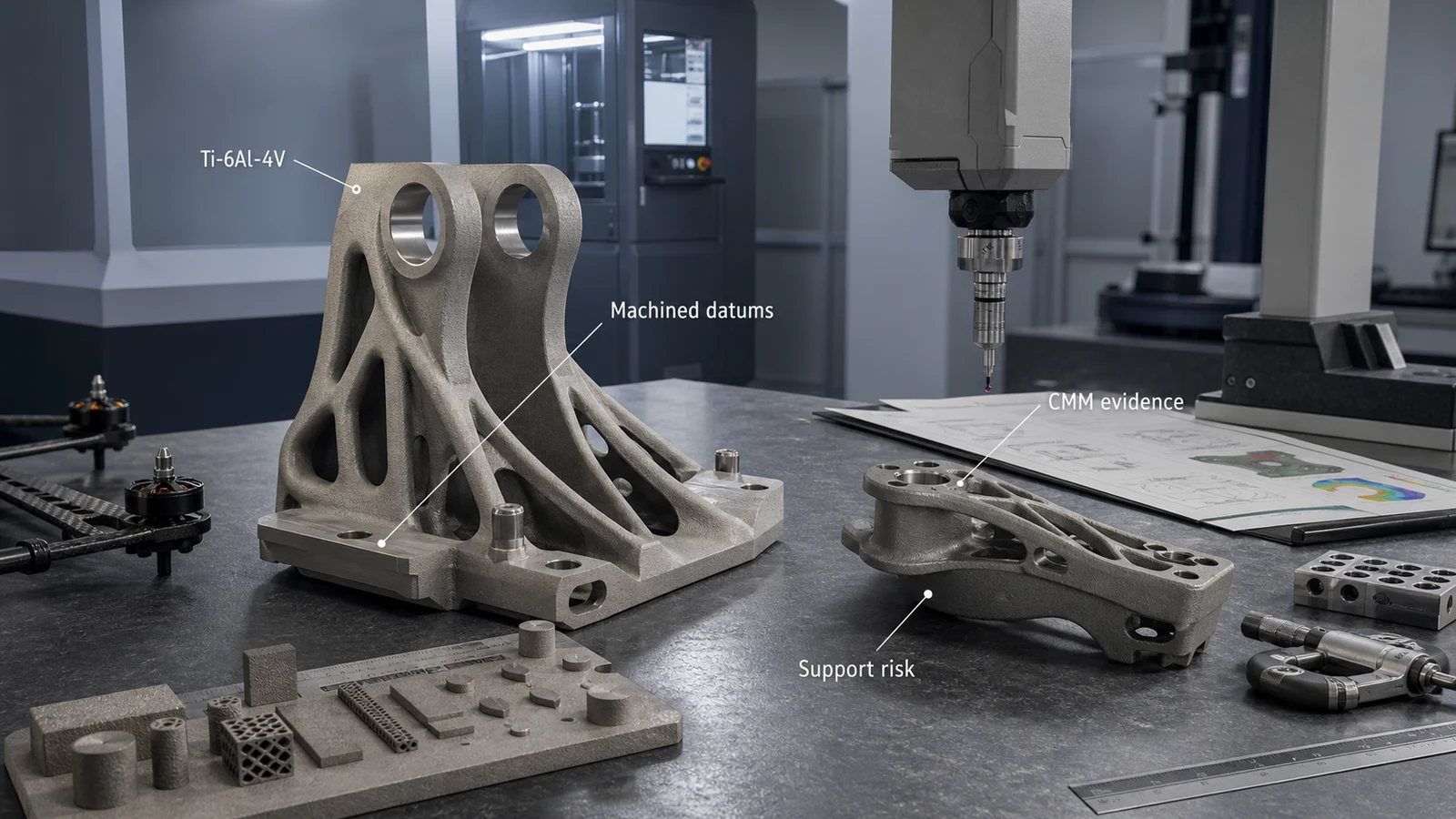
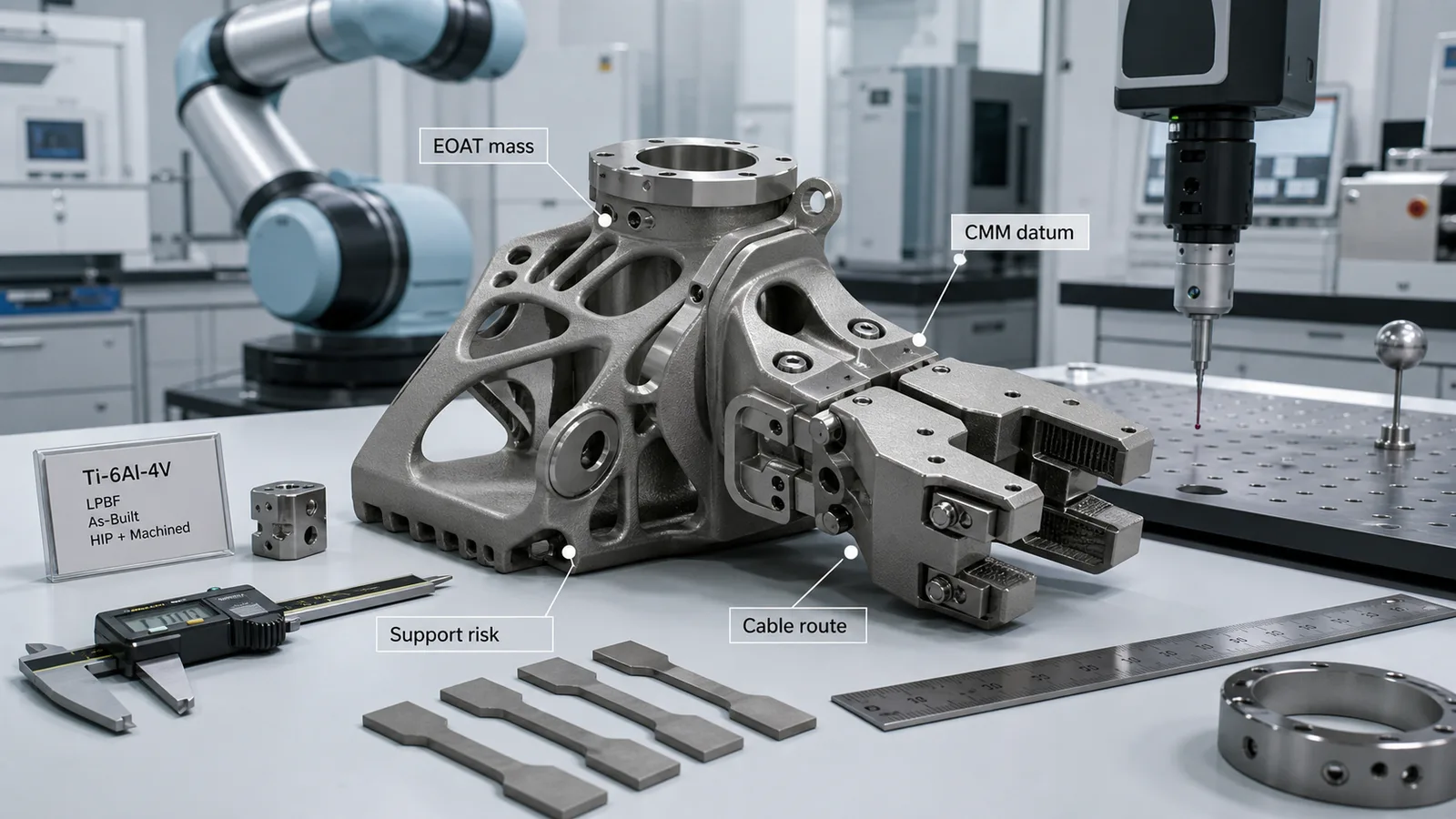
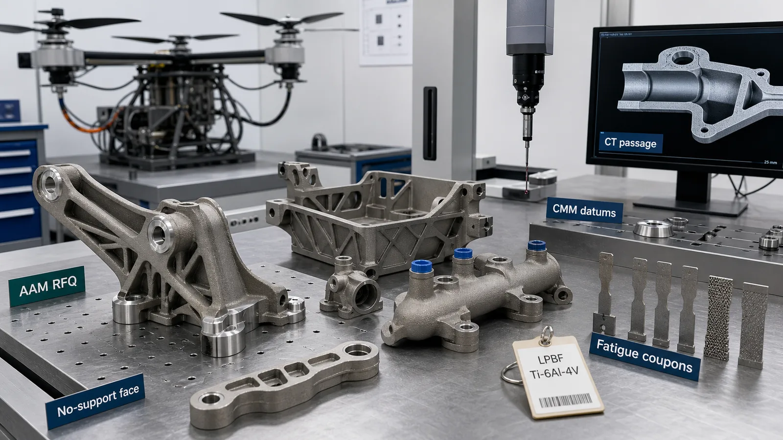
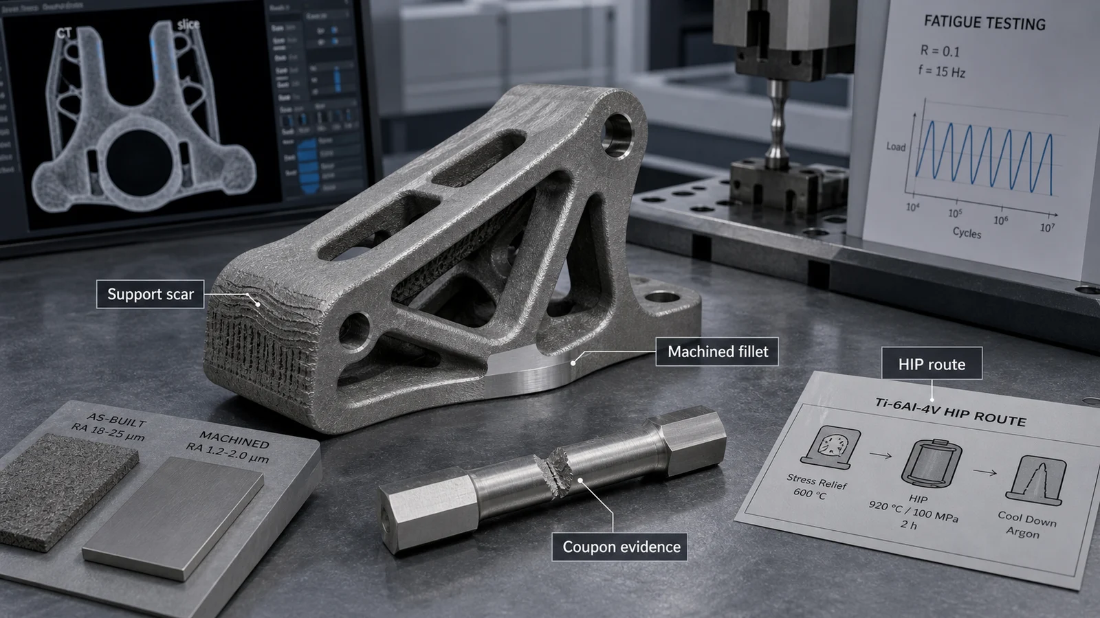
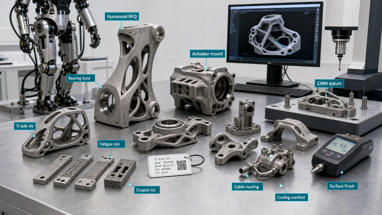
Representative article image; not a customer acceptance record or proof of a qualified manufacturing route. Refer to the cited sources and part-specific inspection records for engineering evidence.
On this page
Drone and UAV teams usually reach titanium 3D printing from a practical conflict. The airframe needs more payload, better stiffness, cleaner packaging, or higher temperature tolerance, but the mass budget is already tight. A printed titanium part can help when it replaces a heavy machined bracket, consolidates several fastened pieces, protects a high-load interface, or turns a difficult payload mount into a controlled geometry.
It is not the right answer for every drone component. Carbon fiber, aluminum, molded polymers, and machined inserts often win on price and mass. Titanium additive manufacturing belongs in the conversation when the part is compact, highly loaded, vibration-sensitive, heat-exposed, difficult to machine efficiently, or tied to a fast-moving low-volume supply chain.
For a broader application map, start with Titanium 3D Printing Applications and use this article for drone and UAV-specific RFQ decisions.
Why Drone and UAV Titanium AM Is Timely in 2026
The current interest is not only hobby drones. As of May 2026, public industry signals show why unmanned systems are receiving more engineering and supply-chain attention:
- The FAA aerospace forecast page includes updated coverage for commercial UAS, advanced air mobility, and remote pilots, reflecting continued normalization of unmanned aircraft activity.
- The U.S. Air Force announced the YFQ-42A and YFQ-44A designations for its Collaborative Combat Aircraft program, showing how uncrewed aircraft are moving into formal aerospace program structures.
- The U.S. Department of Defense has described the Replicator initiative around fielding all-domain attritable autonomous capabilities at scale, which keeps manufacturing speed, supplier readiness, and design iteration in focus.
These signals do not prove that a specific UAV part should be printed in titanium. They do explain why engineers and procurement teams are asking better questions about lightweight hardware, short-run production, alternate suppliers, and documentation-ready additive routes.
For aerospace and defense sourcing strategy, pair this guide with Titanium 3D Printing for Aerospace and Defense Supply Chains.
Quick Answer
Titanium 3D printing is a strong UAV candidate when the part is small enough for powder-bed fusion, valuable enough to justify post-processing, and functionally improved by additive geometry.
Good candidates include:
- Payload and sensor brackets where stiffness-to-weight ratio controls pointing stability.
- Gimbal, camera, lidar, antenna, or electronics mounts with compact packaging constraints.
- Motor mounts, arm junctions, and load-transfer nodes where machined material removal is inefficient.
- Landing, recovery, or launch interface hardware that sees repeated impact or clamp loads.
- Heat shields, exhaust-adjacent brackets, and hybrid propulsion hardware where aluminum or polymer loses margin.
- Small manifolds, cooling bodies, or cable-routing structures where internal passages create value.
- Low-volume replacement hardware where tooling is unavailable and the route can be documented.
Weak candidates include simple plates, low-cost arms, cosmetic drone shells, large flat covers, high-volume commodity parts, and any structural flight part where the buyer cannot fund fatigue, inspection, and qualification evidence.
If the decision is still broad, run the When Not to Use Titanium Additive Manufacturing screen before requesting production pricing.
Drone Part Fit Matrix
| UAV part family | Why titanium AM can help | Main hidden cost | Evidence to define |
|---|---|---|---|
| Payload bracket or sensor mount | High stiffness in compact geometry, fewer fasteners, cleaner cable clearance | Datum machining and CMM setup | Machined datums, bore position, flatness, proof load if needed |
| Motor mount or arm junction | Load-path ribs and local reinforcement without hogging billet | Fatigue and vibration review | Surface condition, support scars, coupons, CMM, torque interface |
| Landing or recovery hardware | Impact resistance and high local bearing strength | Post-processing and replacement cost | Load case, inspection after impact, surface finish at stress risers |
| Thermal or exhaust-adjacent bracket | Better temperature margin than polymers or aluminum in selected zones | Material and heat-treatment route | Alloy condition, oxidation/corrosion exposure, dimensional stability |
| Internal cooling or cable-routing body | Integrated passages and reduced external tubing or clips | Powder removal and CT scope | Cleaning access, CT threshold, pressure or flow test |
| Low-volume sustainment part | Fast route when tooling or legacy supply is constrained | Documentation and repeatability | Build record, material traceability, inspection report, revision control |
The table is intentionally RFQ-focused. A drone part does not become a titanium AM candidate because it looks complex. It becomes a candidate when the system benefit is worth the complete route: printing, heat treatment, support removal, machining, inspection, and records.
Weight Reduction Must Protect Stiffness
Drone structures are sensitive to mass, but stiffness is often the real design target. Removing 20 percent of bracket mass can be a poor trade if it lowers the first resonance, moves a sensor out of alignment, increases motor vibration, or adds compliance at a payload interface.
The right RFQ does not ask only for the lightest possible part. It defines:
- Payload mass and center-of-gravity sensitivity.
- Acceleration, shock, vibration, or landing loads.
- Required interface flatness and bore position.
- No-support surfaces near fatigue or sensor-location features.
- Machined datum pads, bores, threads, and bearing faces.
- Whether the part is prototype, flight test, production, or sustainment hardware.
For topology-optimized load paths and stiffness-driven brackets, see Titanium Additive Manufacturing Applications That Achieved Real Weight Reduction. The same logic applies to UAV hardware: mass removal must improve the aircraft, not only the CAD screenshot.
Vibration and Fatigue Are the Main Boundaries
Small UAV parts can see high-frequency vibration from motors, rotors, propellers, payload isolation systems, launch events, and landing loads. A printed titanium bracket may pass static strength and still be a weak design if a rough supported surface, sharp rib transition, or thin-to-thick section change sits in a cyclic tensile region.
High-risk features include:
- Support scars on loaded undersides.
- Printed holes used directly for precision fasteners.
- Sharp internal corners in topology-optimized ribs.
- Thin ribs tied directly into thick bosses.
- Lattice transitions near bolted joints.
- As-built surfaces at clamp or bearing locations.
- Long cantilevered payload arms with low modal margin.
Do not rely on alloy strength alone. Ti-6Al-4V can be the right alloy and the part can still fail the mission because the load path, surface state, or evidence plan was weak. Use the Titanium 3D Printing Fatigue Design guide when the part sees vibration, repeated landing loads, rotor-induced excitation, or payload pointing requirements.
Material Choice: Ti-6Al-4V Is Usually the Starting Point
For most drone and UAV structural hardware, Ti-6Al-4V is the practical first review. It offers high strength-to-weight performance, broad AM supplier familiarity, and a mature post-processing conversation. Ti-6Al-4V ELI may be relevant when ductility, fracture behavior, or tighter interstitial control is part of the acceptance basis, but it should not be specified only because it sounds safer.
CP titanium is a different conversation. It can be useful for corrosion resistance, ductility, or chemical compatibility, but it is not a default substitute for a high-strength structural UAV bracket.
The material line in the RFQ should include the alloy, condition, post-processing expectations, documentation needs, and whether substitutions are allowed. For a deeper alloy comparison, use Titanium AM Material Selection: Ti-6Al-4V, ELI, and CP Titanium.
Process Choice: LPBF Is Often First, but Not Automatic
LPBF is usually the first process reviewed for compact drone parts because it supports fine geometry, ribbed brackets, internal channels, and small structural nodes. It also brings powder removal, support contact, thermal distortion, and surface finish decisions into the quote.
EBM may be reviewed when the supplier has a controlled route and the geometry tolerates the process-specific surface and feature profile. DED is usually a better fit for larger near-net titanium stock, repair, or feature addition rather than fine UAV brackets and small payload mounts.
The process should follow the part function:
- Use LPBF for detailed payload brackets, compact mounts, small manifolds, and high-value structural nodes.
- Review EBM only if the supplier route, surface expectations, and part geometry fit.
- Review DED for larger near-net or repair-style UAV hardware that will be machined afterward.
- Use machining, carbon composite, aluminum, or molded parts when AM geometry does not improve the aircraft.
The Titanium AM Process Selection: LPBF vs EBM vs DED article explains how process choice changes support strategy, inspection, machining stock, and cost.
DfAM Rules That Matter for UAV Hardware
UAV parts tend to be compact, crowded, and interface-heavy. That makes DfAM review more important, not less. The CAD model should define which surfaces can remain as-built and which must be machined or protected.
Useful UAV DfAM rules include:
- Keep supports away from fatigue-critical and sensor-location surfaces.
- Add machining stock around bores, threads, bearing lands, and datum pads.
- Use generous rib transitions instead of sharp lightweighting cuts.
- Keep powder-removal access realistic for enclosed channels or hollow arms.
- Avoid fine lattice regions where cleaning and inspection are impossible.
- Place cable routing so it does not create powder traps or weak load-path necks.
- Define no-support faces before the supplier chooses build orientation.
For support, overhang, thin-wall, and trapped-powder rules, use Titanium DfAM Rules for LPBF and EBM. For enclosed cooling or routing features, add the powder-removal and CT assumptions from Titanium 3D Printed Internal Channels.
Datum Planning and Inspection
A drone payload mount often fails the business case when the quote misses inspection and machining. The printed shape is only part of the route. The accepted part may need bores machined after stress relief, a sensor face skimmed to flatness, a CMM report tied to datums, and traceability for the build lot.
Typical UAV evidence includes:
- CMM report for datum pads, bore axes, motor interface geometry, and sensor-location faces.
- Surface roughness checks on fatigue or clamp regions.
- CT for enclosed channels, hidden powder traps, internal defects, or thin structural features when risk justifies it.
- Tensile or process coupons when the build condition must be documented.
- Proof load, vibration, leak, pressure, or balance checks when the application requires them.
- COA, COC, build record, powder lot, heat-treatment batch, and inspection report.
Do not request CT, coupons, and full traceability on every prototype by default. Do request the evidence that answers the risk question. The broader framework is in Titanium AM Qualification and Inspection Evidence, and datum planning is covered in Titanium 3D Printing Tolerances: Datum Planning and CMM.
Cost: Compare Delivered Hardware, Not Printed Shapes
Titanium AM can reduce material waste, assembly count, or lead time, but drone parts are often cost-sensitive. A print-only price can look attractive until the buyer adds stress relief, support removal, machining, fixture work, inspection, cleaning, documentation, and revision iteration.
Cost is easier to control when the RFQ separates necessary work from optional work:
- Machine only functional datums, bores, threads, and interface faces.
- Leave noncritical exterior surfaces as-built when they do not affect fatigue, aerodynamics, assembly, or cleaning.
- Use CT only where hidden geometry or defect risk affects acceptance.
- Avoid titanium when carbon fiber, aluminum, or polymer already meets the load, temperature, and evidence needs.
- Allow the supplier to recommend geometry changes before the drawing is frozen.
For quote normalization, use Titanium 3D Printing Cost Drivers: How to Reduce RFQ Price and the Titanium AM RFQ and Procurement Guide.
RFQ Scenario: UAV Payload Mount
Consider a Ti-6Al-4V payload mount for a UAV inspection platform. The payload is heavier than the previous sensor, the envelope is fixed, and the mount must keep two optical axes stable during vibration. A machined billet design is stiff but heavy. A carbon composite bracket is light but adds local insert and clamp concerns. A titanium LPBF route may be attractive because the load path can be ribbed around the payload, cable clearance can be integrated, and only the datum pads and bores need machining.
A weak RFQ says:
Please 3D print this UAV payload bracket in titanium.
A better RFQ says:
Please review this UAV payload bracket for Ti-6Al-4V LPBF. Functional features are the four payload bores, two airframe mounting bores, and three machined datum pads. Noncritical external ribs may remain as-built after support removal and cleaning. The part sees vibration and repeated landing loads, so please identify support locations, protected surfaces, stress relief, machining stock, CMM scope, material traceability, and whether CT, HIP, or coupons are recommended for this risk class. Please include any DfAM changes that reduce support contact, mass, or machining time without moving the payload interface.
The second RFQ is more work to write, but it protects the buyer from comparing a printed shape against a delivered accepted part.
UAV Titanium AM RFQ Checklist
Send the supplier:
- STEP file and drawing with datums.
- Target alloy and material condition, usually Ti-6Al-4V unless another route is justified.
- Quantity, prototype or production intent, and target lead time.
- Payload mass, acceleration loads, vibration concern, impact or landing loads, and temperature exposure.
- Functional interfaces: bores, threads, clamp faces, sensor location faces, datum pads, and bearing lands.
- Surfaces allowed to remain as-built and surfaces requiring machining or finishing.
- No-support regions and support-removal access limits.
- Internal channels, cable routing, or hollow structures with cleaning access requirements.
- Required post-processing: stress relief, HIP if justified, machining, polishing, cleaning, coating, or passivation.
- Inspection and documentation: CMM, CT, roughness, coupons, proof test, balance, COA, COC, build record, powder lot, and inspection report.
- Permission for the supplier to recommend DfAM changes before final quotation.
If the supplier cannot explain support strategy, machining assumptions, inspection scope, and acceptance evidence, the quote is not ready for comparison.
Bottom Line
Titanium 3D printing can be valuable for drone and UAV parts when the part is compact, high-value, interface-heavy, vibration-sensitive, or constrained by packaging and lead time. The strongest cases are payload mounts, sensor brackets, motor or arm junctions, thermal-adjacent hardware, and low-volume sustainment parts where additive geometry changes the aircraft outcome.
The weak cases are simple shapes, low-cost covers, commodity arms, and any structural flight part where qualification budget is missing. For UAV hardware, the real decision is not “Can this be printed?” It is “Can this route deliver a lighter, stiffer, inspectable, documented part at a cost the program can accept?”
For an RFQ review, send CAD, drawing, load context, target alloy, quantity, lead time, post-processing expectations, and inspection requirements through the RFQ inputs page or email info@szcomo.com.
- Drones
- Uav
- Lightweighting
- Aerospace
- Defense
- Fatigue
- DFAM
- RFQ